
Cost and Specs
Total cost: approx. US$15 (parts only; you need tools such as soldering iron etc.)
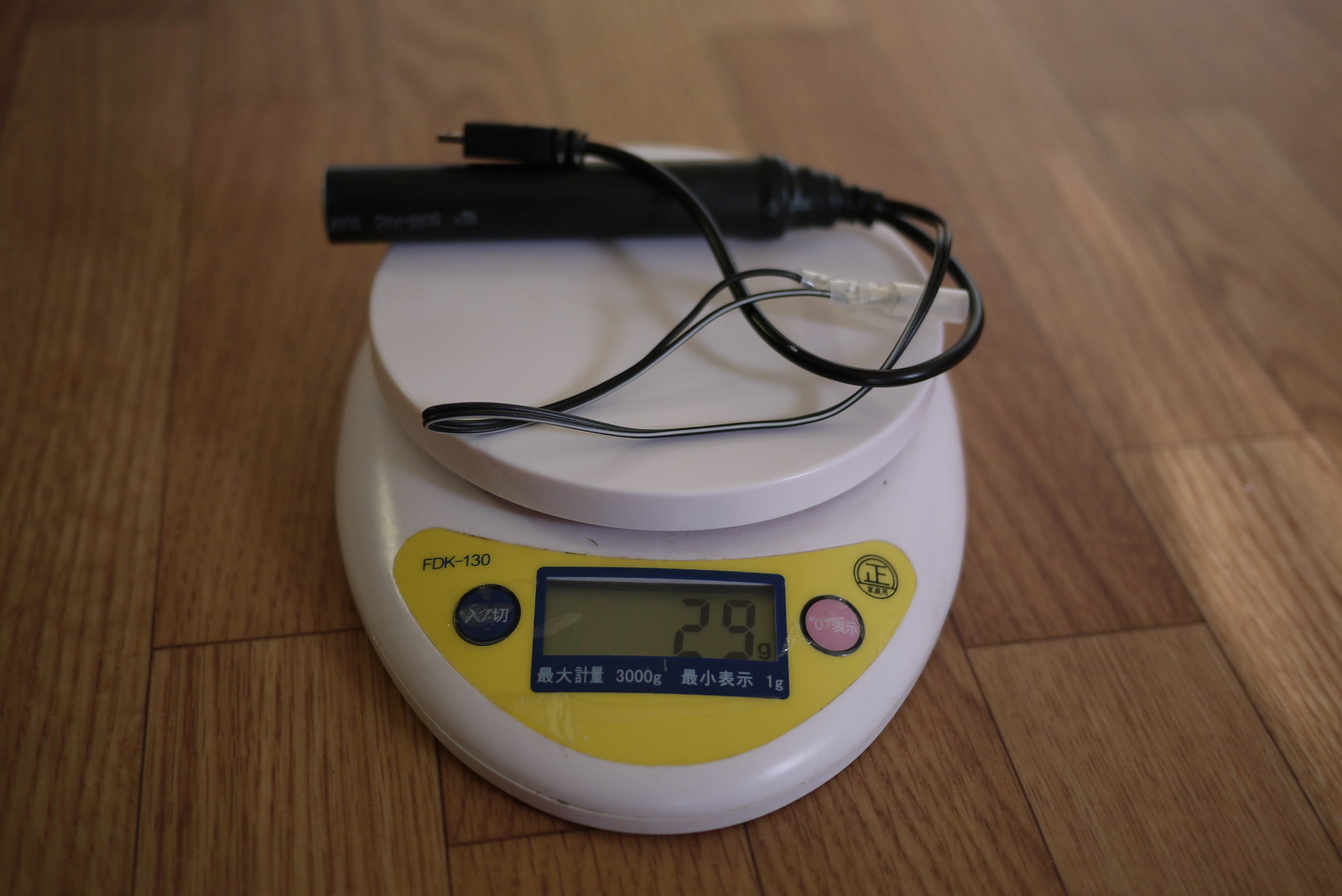
Weight: 29 grams
Weatherproof: Yes
Output: 5 volts DC (USB standard)
Input: 6 volts AC
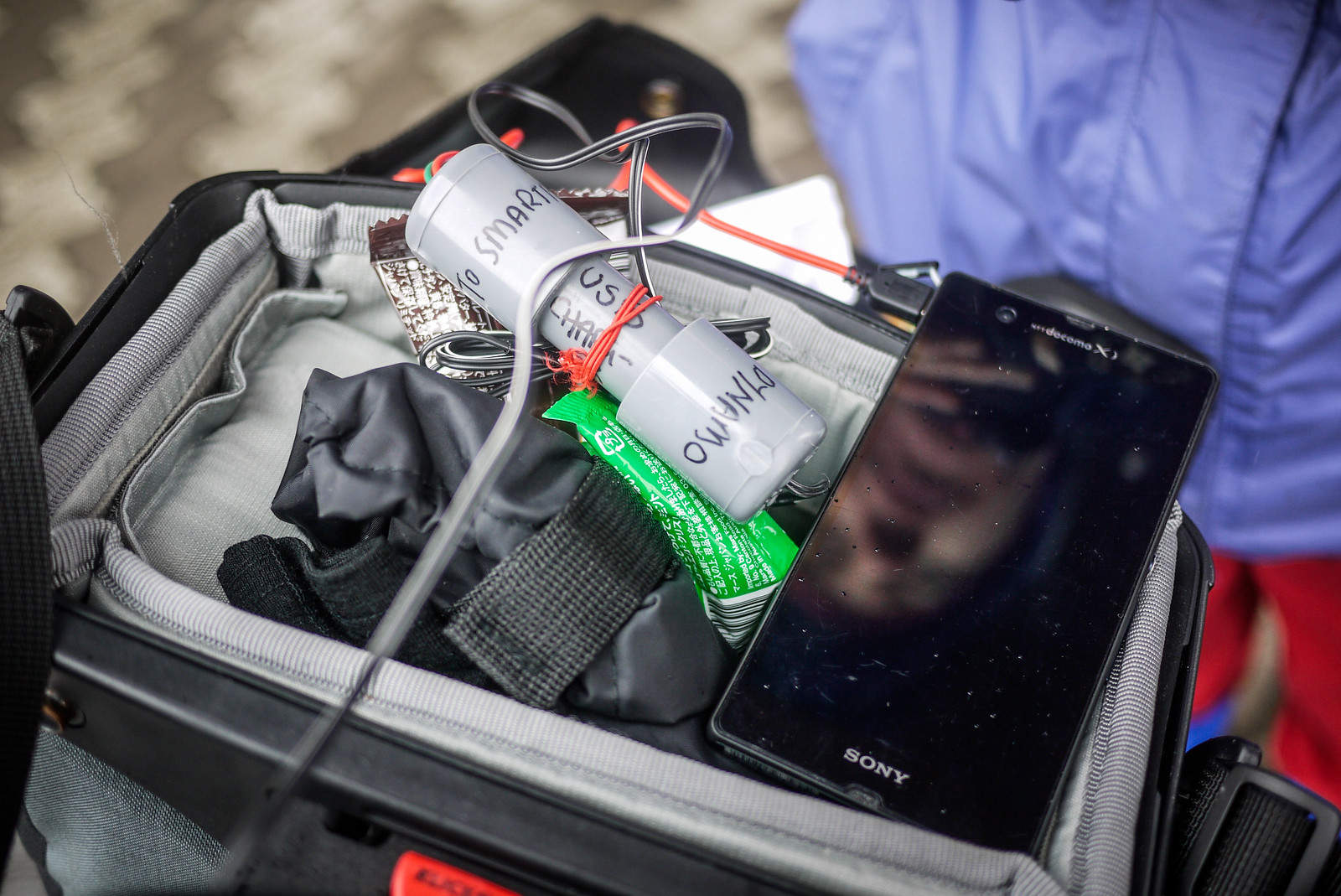
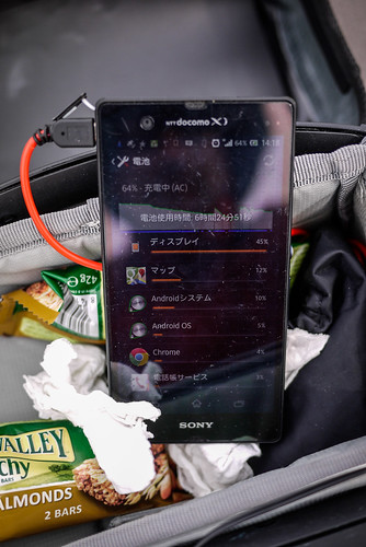
Efficiency: Will charge a Sony Experia Z smartphone at a rate of approximately 1% per 1km (with the smartphone turned off).
Charge start: 5.5km/h
Weight
What this device does
When charging your smartphone using a wall charger or your laptop’s USB, the electricity going into your phone is direct current (DC) at 5 volts. A bicycle dynamo hub, however, usually creates electricity in the form of alternating current (AC), at 6 volts. So, we’ve got to change the electricity created by the dynamo hub (6V AC) into the same type as what comes out of your smartphone wall charger or your laptop’s USB (5V DC). That’s what this device does.
Disclaimer: I know nothing about electronics. This charger has worked well for me so far (about 1,000km of cycle touring), but it may turn on you and eat your smartphone’s innards alive, rendering it a useless shell. Also, note that in very hilly terrain where constant high cycling speeds are expected (on the downhills), the charger may not cope with the high voltage output from the dynamo (voltage output often varies depending on speed) (thanks to commenter Prashant for the real-world observation). This may mean a need to unplug the charger on long, fast downhills. If you’d rather let someone else take the responsibility for your delicate electronics, check out the Bright-Bike Revolution (amazing value for a solid charger) or the Busch & Mueller Luxos IQ2 headlight with USB charging built in, or the Tout-Terrain Plug II.
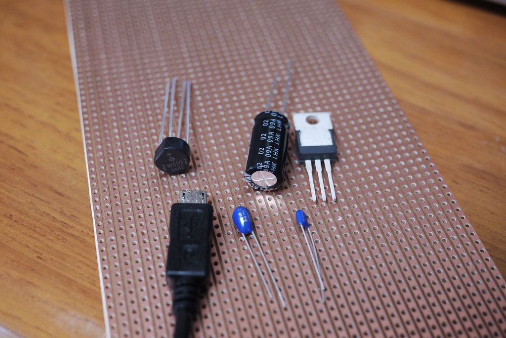
What you need
- Parallel stripboard (example)
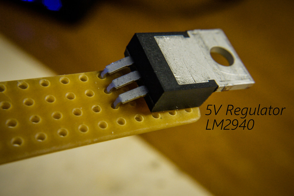
- 5 Volt Regulator LDO LM2940 (example – max input voltage 26V) (changes 6V to 5V)
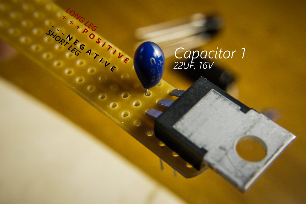
- Capacitor 1 (Tantalum bead, 16V 22µF) (example)
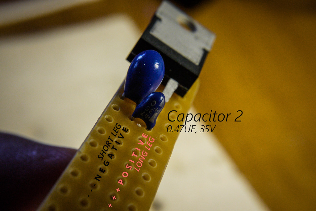
- Capacitor 2 (Tantalum bead, 35V 0.47µF) (example)
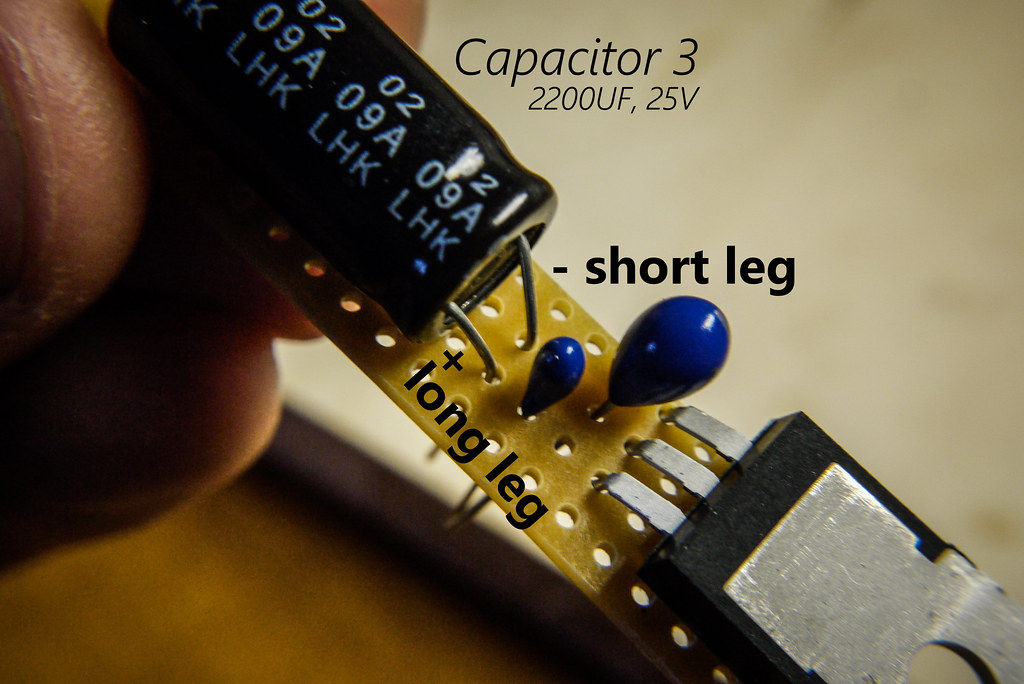
- Capacitor 3 (Electrolytic capacitor, 25V 2200µF) (example)
- The capacitors help keep the flow of electricity steady as you slow down and speed up on your bike (see Wikipedia for more).
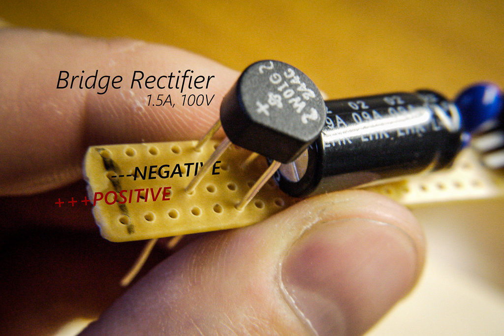
- Bridge Rectifier, 1.5A, 100V (example) (changes the input from AC to DC)
- Micro-USB terminal (example; you’ll cut off the big USB end and keep the small end, to plug into your device)
- Wire and terminals to attach to dynamo outlets
- A case of some kind to hold the electronics
How to Make it
Step 1
Cut the veroboard (stripboard) into an oblong, 4 holes wide by approximately 25 holes long. I did this by scoring the board with a craft knife on both sides and then snapping it.
Step 2
Start to populate your board. On the capacitors, the long leg is positive. Click on the photos for a larger version.
Step 3
This step can be tricky…aligning the bridge rectifier in place. Note the polarity (positioning of the negative and positive legs).
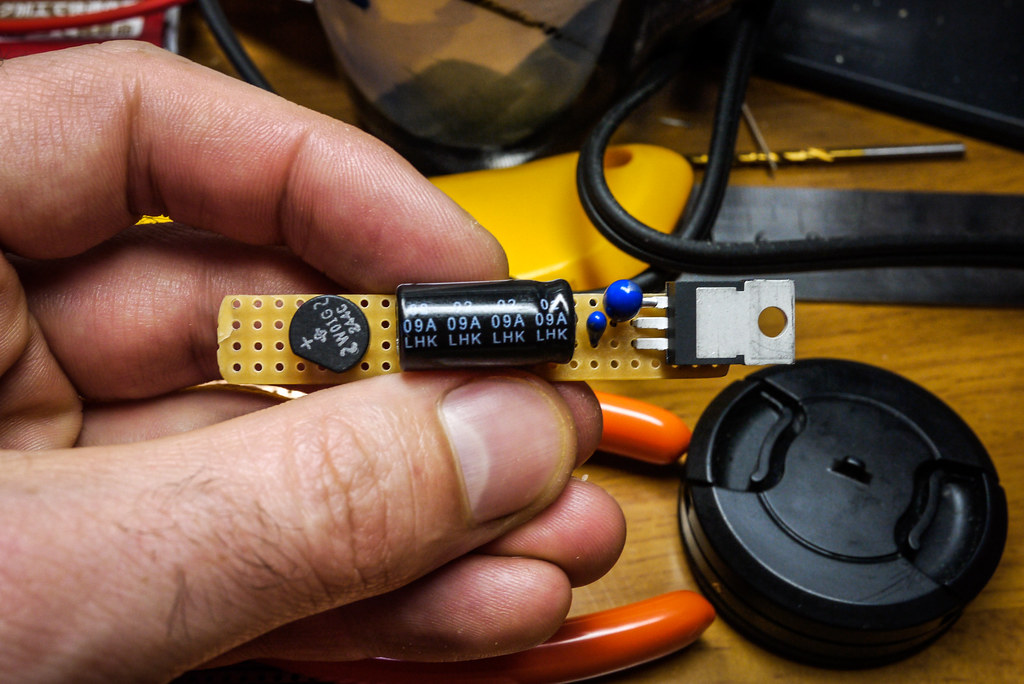
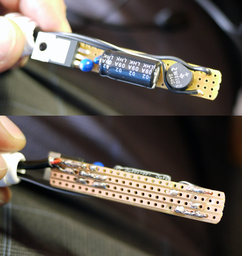
Looking from the top, your board should now look something like this.
You can now go about carefully soldering the parts in place at the rear of the board. Take care not to overheat the parts, and make sure not to ‘connect’ any of the copper strips on the stripboard with stray bits of solder.
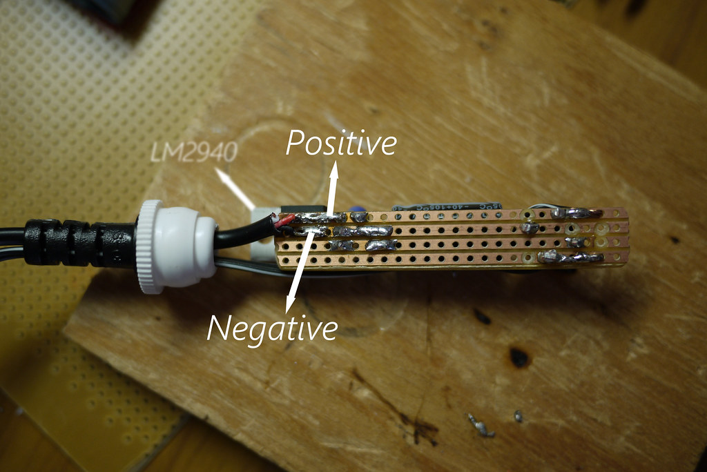
Post-soldering should look something like below. Ignore all the drill-marks, except for the one at the bottom. You need that one to stop current going directly to the regulator (LM2940). Holes can be made by hand-turning a 5mm drill bit.

Step 4
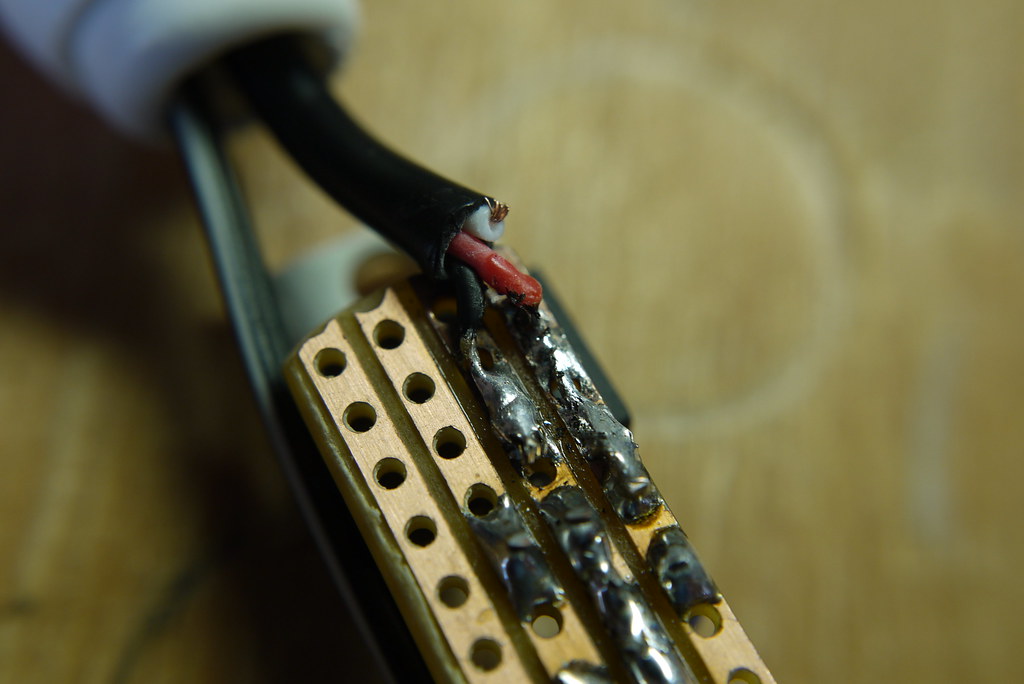
Prepare your micro-USB connector by butchering a cheap USB to micro-USB cable, discarding the big USB end. We will attach this to the circuit-board, and it will plug into your smartphone. Frustratingly, USB cable inner wire colors are sometimes different (like, green for negative). But most of the time, they will be red (positive), black (negative) and white (data). You won’t be needing the white wire, so you can cut it short.

Step 5
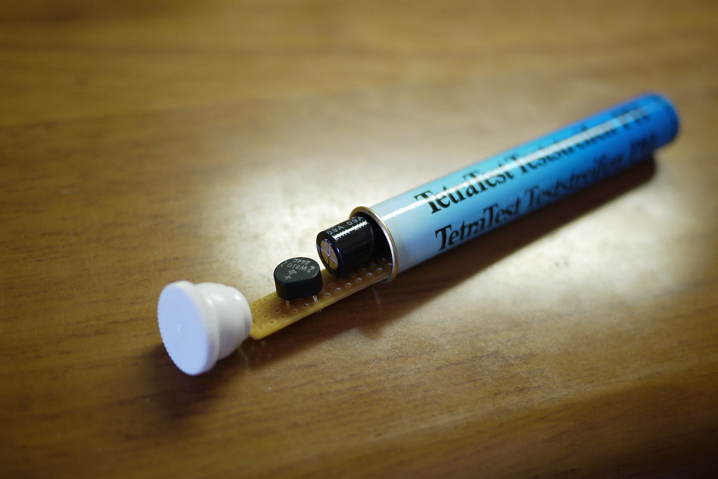
Before attaching the micro-USB cable to the circuit-board, a suitable case needs to be found. I happened to have an old fish-tank PH level tester container hanging around that was a perfect size.
Step 6
Container sorted, time to thread the cables through the openings and solder them to the circuit board. I first attached the micro-USB cable. Red on the positive line, black on the negative line.
Next, attach the wires that will run from the dynamo hub. The polarity (negative and positive direction) here doesn’t matter at all; the bridge rectifier has magic fairies inside that sort all that out.
Step 7
Install the circuit board in a suitable container. Before sealing the container up properly, now may be a good time to hook the unit up to a dynamo hub and smartphone to check that everything is working.
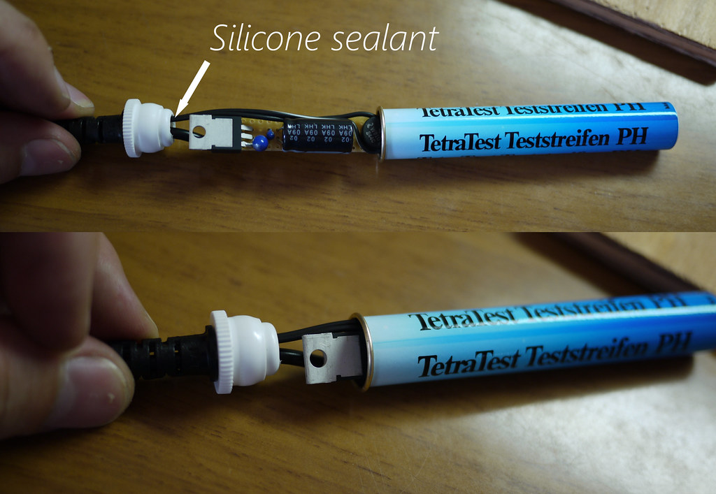
Step 8 (optional)
This step is not essential, but I wanted to make this unit as weather-proof as possible. Using a couple of different size heat-shrink tubing, I covered the whole thing up, making it very weather-proof.
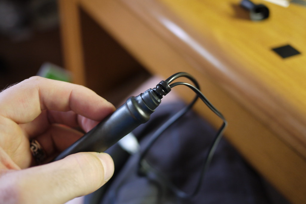
Step 9
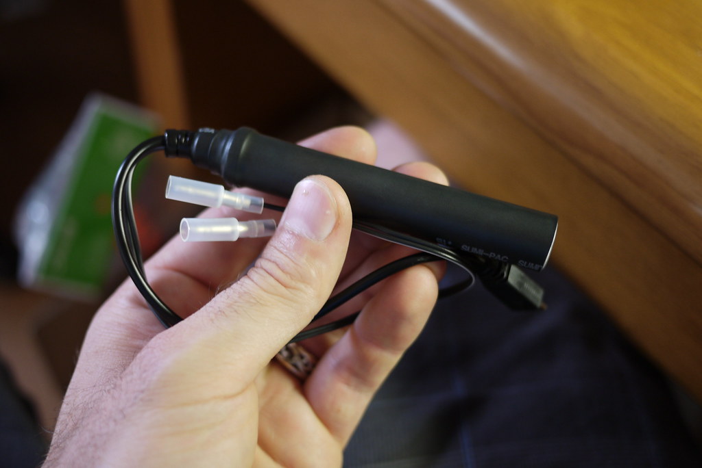
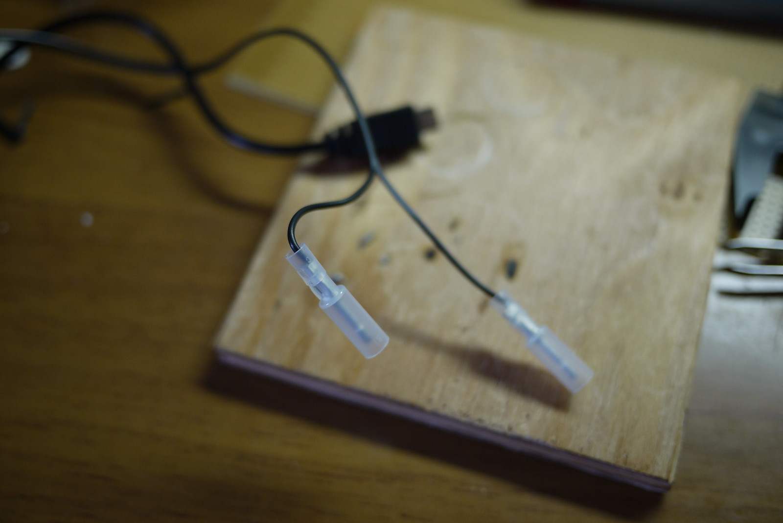
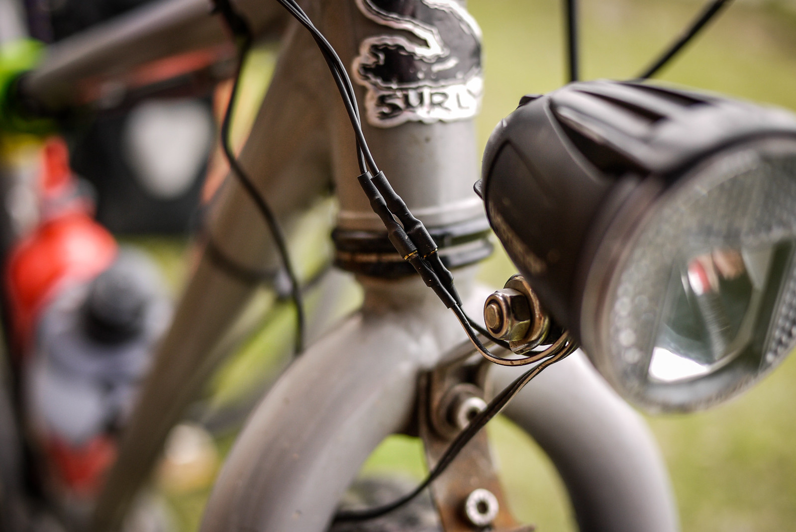
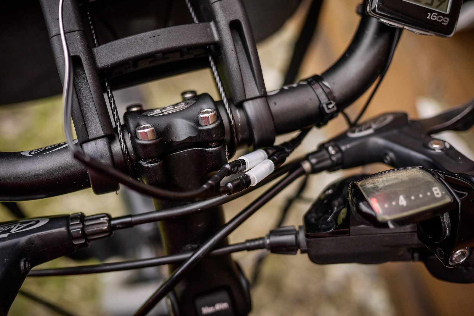
I wanted to be able to easily attach and remove the charger from my bike. The only time I use it is when I am cycle touring (about twice a year). This was easily done by using simple male/female connectors. The wire running from my hub to the female connectors is on my bike all the time, and I can just connect the charger when I need to.
Wrap-up
Performance in the real world
This is the second charger I have made (using the exact same circuitry). The first one ended up in a PVC pipe casing, which is ugly and bulky. It works exactly the same as this new slick-cased version. Using the PVC-pipe-case version, I was able to get around 1% charge for every 1km pedaled on a laden, flat-terrain four-day cycle tour (with the phone powered off). That was charging a Sony Experia Z smartphone, which has a very large battery (2330mAh). With an iPhone, with its smaller 1440mAh, this might be more like 2% charge per 1km.
In any case, with the phone powered off, it will charge fully over a full day of cycling. It does not put out enough charge to keep up with intensive computing tasks like Google Map Navigation. That is, with the screen on all the time, plus the GPS running, the battery will still run down even while charging.
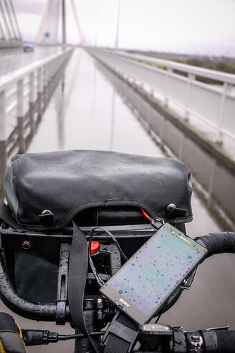
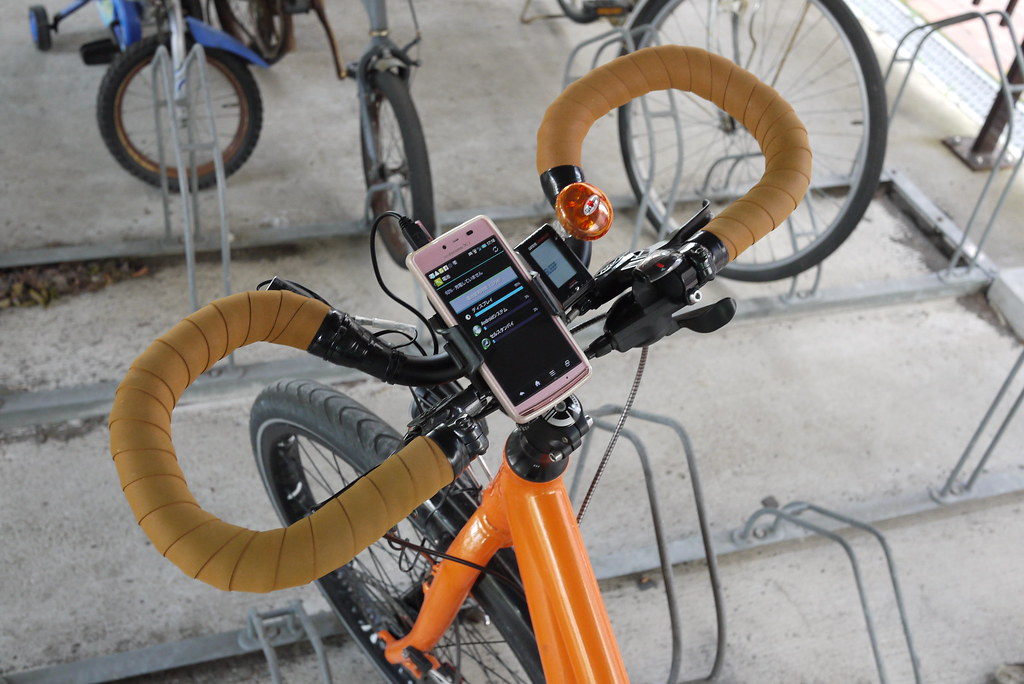
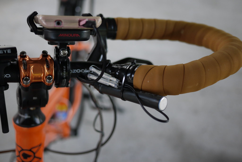
My wife has claimed this new version as her own, so I am still stuck with the PVC pipe version. On her bike, this is the set up we have at present (she doesn’t use a handlear bag). Here, the charger is attached using a cable tie, in the photo at the top of this post, we have attached a velcro strap, which will make attaching/removing the charger easier.
Update (2014/06/08)
Thanks to commenter Prashant, I’ve just found out that you can buy a perfectly good charger for only US$30 or so: The Biologic ReeCharge Dynamo Kit. See the demo on Youtube https://www.youtube.com/watch?v=tnlB68KulcE, and looks like you can get it on Amazon: http://www.amazon.com/BioLogic-Reecharge-Dynamo-Kit/dp/B006OSQUNI. For that price, the only reason you’d ever need to make your own device is if you’re really into DIY! Official page for the kit here: http://www.thinkbiologic.com/products/reecharge-dynamo-kit-micro-usb-cable
Update (2014/09/21)
Note Viktoras’s comment that the Biologic Reecharge may not give enough output for some devices.


119 thoughts on “DIY Bicycle Dynamo USB Charger for Smartphones and Battery Packs”
We did this for a school project, and you’ve been a great help for us. We only have one problem: when we try to charge, it only works for about 1 sec. after this it goes dark. we have no idea on what causes this, but need to fix it fast. any ideas on what might be causing this issue? we are using schkottky diodes, a 3000 microfarad elco, two tantalums of 22 and .47 microfarad and a lm2940CT regulator. Help is very much appreciated.
Hey, thank you for the feedback. One possible problem may be with your smartphone/device that you are trying to charge. Some phones require more amperage and/or a very stable input in order to charge. I’ve not had a problem so far with the phones I’ve tried (Sony Xperia Z), but you may want to try using the dynamo charger just to charge a separate battery, and use the battery to charge the phone. Auxiliary high-capacity USB batteries for charging smartphones tend to be less sensitive to fluctuations in charging input, I think.
Thank you so much for your encouragement! I really appreciate it! I only hope to share what I’ve personally learned and experienced to be Truth in my own life! Have a fantastic day!
can i get the schematic diagram of this charger?
Hi Kishen. Try some of the links at the top of the post. They have schematics for this design.
Same as Prashant, I am puzzled with how this circuit works for so many people. Unless you keep your speed low all the time, the voltage from the hub can easily go over 50V under light load, frying the input cap and/or the regulator (which almost never have an overvoltage protection inside, LM2940 included, but can survive some transients for couple of ms).
That’s why you will find some kind of overvoltage protection in almost all available hub dynamo power supplies. Usually it’s a voltage limiter (zener, varistor or zener-transistor limiter) that absorbs excess energy, coupled with a heatsink or thermal switch, or sometimes it’s a high voltage series transistor, like in the 2nd gen Biologic ReeCharge.
The former solution is cheaper, all it takes is a varistor and a thermal switch, take a look at forumslader.de for example.
Well in the very least it didn’t get fried on some recent long (30min) fast (40km/h) downhill stretches recently…I wonder if the Shimano Alfine dynamo has an output limiter? Not sure…
I just wanted to point out that there is a possibility of damage due to overvoltage, and that adding some kind of protection is relatively easy. For example Shimano SM-DH10, Lightcharge OPS or internal/external diy version.
Not sure about the Alfine hub, but the majority of Shimano hubs (including my DHT780) don’t have a limiter.
In any case glad to hear that yours is still going strong :).
When I tested this circuit, it cut out (to 0V) whenever the input went overvoltage, and stayed there until the voltage came back down again. I suspect the transient voltage protection in the LM2940 is active in cutting the input, but can’t guarantee that.
The reason why it works is simple. The hub dynamo is a current limited device. This basically means that – as long as you have it loaded sufficiently (approx 500ma) it will put out about 6v with little relationship to speed. This is documented graphically on many German technical websites – easy to see even if you can’t read German! If you remove the load of course the voltage will climb in a linear fashion with increasing speed – but that’s not what we are doing here is it! There are many, many posts at candlepower forums that discuss the hub dynamo as a current limited device with various levels of technical insight. Perhaps we just have to forget about ‘measuring voltage’ and focus on the current – which after all is what powering devices and charging batteries is really about.
It’s all about ‘measuring voltage’ when it comes to breakdowns.
Having a phone as the load does not guarantee 500 mA under all conditions. I think it is safer to treat the hub dynamo as a voltage source with a certain output impedance (which will of course limit the current for high loads, or once a breakdown occurs somewhere in the charger/load).
how to use that?can you explain fo me?
Hey Muhammad. This device connects to a hub dynamo (or bottle dynamo) on a bicycle, and converts the electricity from the hub to 5V USB power. Connect the wires going into the device to the hub, then connect the USB connector to your phone, and you can charge the phone. Does this help?
i had no knowledge about circuit design
but i wish to build a dynamo handphone charger based on yours
can i ask what is the function of capacitor in this thing
and why you use two type of capacitor
that is tantalum and electrolye
what is the different ??
From what I understand, the capacitors help keep the flow of electricity constant (https://en.wikipedia.org/wiki/Capacitor#Hydraulic_analogy). Apart from that, I have no idea why there are different types and different sizes, sorry 🙂
I make this with your step by step guide. It doesn’t work please help me. I am using bottle dynamo 12V6W.
Thanks for the comment!
This design should (I think?) work with a 12V input. But, it is likely to overheat quite easily. See this comment here for advice: https://www.14degrees.org/diy-bicycle-dynamo-usb-charger-for-smartphones-and-battery-packs/#comment-215029.
Otherwise, you might want to check the following:
1) Did you overheat any of the parts when soldering them?
2) Are any of the copper ‘strips’ on the stripboard mistakenly connected with solder?
3) Did you make sure to make the drill mark where you needed to?
4) Are you using the correct wires from the micro-usb cable?
Apart from that, I really have no idea about what you can do to make it work with 12V6W, sorry. Like I said at the beginning of my blog post, I know next to nothing about electronics 🙂
Hi.
Where are the schematics?
Hey Artis, check out the blog post by Mr. Howdy: https://howdy.wordpress.com/2010/09/27/diy-hub-dynamo-usb-charger-inside-handlebar/. My version here is pretty much based on that version.
Rob,
Today morning just stumbled upon this website. Now after writing few comments & responding to your replies, I have noticed that this is your web site & you are the Admin.
So, went deeper & saw your Japan trip blog.
Very nicely compiled. Feels like being there & experiencing the trip to some extent. !!
few question if you don’t mind.
what kind of camera you are using on this trip?
Which is your present touring bike? I noticed one with internal gear rear hub if I am not wrong.
Many Europeans visit India to experience highest motorable mountain pass (Khardungla). Have you visited India anytime before ?
Sorry for the Q’s without going thru whole of your site.
I thing I got most of the answers.
I think getting to know all of your adventures!
Great!
Yes I tried with biggest heat sink I could possibly have.
No linear regulator can work with my Shimano dynamo.
Need DC-DC switched mode regulator. I ended up buying Biologic recharge kit for $30. This is working for me in most adverse conditions.
I tried myself to hook up DC-DC switched mode regulators, but bibl of materials was close to $20+. So spending $30 was obvious choice to get commercial device.
Hope this helps
Thank you very much for the insight, Prashant. I have updated the disclaimer in the main body of the article to take into account your experiences!
Thanks for taking my comments positively !
Good that we both hold similar views about Biologic product.
Right now I just ordered a ReeCharge kit 🙂 The charger in this post is one that my wife is using (she doesn’t cycle very fast even down the hills). For $30, you can’t really go wrong, so we’ll see how the BioLogic one goes.
I think in the new version they are including male DC connector to female DC-micro USB connector.
I hope it should workout for you.
Happy Cycling & lot of Green Recharging !!
Hi – I’m the Ed who put the first reply on this page.
My experiences with this circuit are outlined here: https://forum.ctc.org.uk/viewtopic.php?f=5&t=79811&p=779902
Basically, the problem which Prashant predicts is somewhat true. The voltage of a hub dynamo does rise very high, if there is no, or little, load. I.e, if you are not charging anything.
If you are charging something, which takes the 500mA or so the dynamo can provide, the voltage is kept down – to close to 6V in many cases (or whatever the regulator needs).
The reason why the circuit is still pretty successful for most people is that the LM2940CT seems to have a transient voltage cutout, which protects the regulator if the voltage surges. And people are either riding fairly slowly OR always charging something when the unit is on/plugged in.
The problems on my link are basically an unfortunate set of circumstances which only apply if accelerating too fast with a ‘smart’ phone attached. By cutting out, the LM2940 does effectively protect the phone and itself though. The only real risk is to the 25V smoothing capacitor.
As for the Biologic Reecharge, unless they changed the circuit it’s no more advanced than this one. See https://yacf.co.uk/forum/index.php?topic=40524.msg952080#msg952080 – it appears to use a L7806CV linear regulator, which is actually less efficient than the LM2940CT. And the linked example also failed the same way as Prashant experienced.
Here are some ideas for overvoltage protection: https://forum.ctc.org.uk/viewtopic.php?f=5&t=86041&p=788434
Ed, thank you for the feedback! By the way, the ReeCharge unit is, at the very least, a different shape to the one photographed in that forum link. I tried prying mine open (it arrived in the mail about 5 days after ordering it) to see what’s inside, but couldn’t get into it…
Is the new ReeCharge longer in shape than the one on the yacf link?
I see in the literature for the ‘ReeCharge Dynamo Kit’ (not the original one with the power pack) there’s mention of ‘Safety circuitry in power converter protects battery against power spikes.’ Maybe that’s new, and explains the extra space required.
Hey Ed, it is indeed longer than the one linked to there…here is a picture of the one I have:
Exposed wire ends go to the hub, and included is a micro-USB adapter.
Brilliant. Do post an update on how well the Biologic works. If it does everything it should, at that price DIY only makes sense for the curious!
And by the way, I just checked out the ReeCharge Dynamo Kit…that is amazing value! I did not realise they had come out with that product…way cheaper than anything else on the market!
ReeCharge Dynamo Kit: https://www.amazon.com/BioLogic-Reecharge-Dynamo-Kit/dp/B006OSQUNI
Youtube demo: https://www.youtube.com/watch?v=tnlB68KulcE
I am disappointed in Biologic Reecharge. Its max cahrging 500 mA, and unfortunatly that I notice only after purchase. Actually my Sony Xperia Z1 consumes 750 mA. I check different devises: Biologic, Rom Tomson schema, and Galgut schema. At 20 km/h speed charging at 420, 460, 760! mA respectively. So I have answer for all who wants to buy B..R.. , its not worth the money. If you have smart phone- make Galgut device, if simple phone- Tomson schema is OK.
Viktoras, thank you so much for the report! I also could not charge my Sony Xperia Z using the Biologic Reecharge.
I contacted Biologic about this problem, and they suggested to try charging another device, in order to diagnose what the problem is. In the end, I haven’t had time recently to re-connect the Reecharge to my bike and test different devices…
So, your information here is very important! I will copy and paste your comment here to my reply to Biologic…sounds like I need to get a refund! Perhaps you should contact support at Biologic and get a refund too!
By the way, what is the ‘Galgut schema?’
As I understand it, the ‘Galgut schema’ is the circuit you see here: https://www.arenddeboer.com/bike-mounted-usb-charger – it’s the same as yours, but with a ‘boost capacitor’ on one half of the rectifier. That can be achieved by one bi-polar capacitor or, in the case of the linked diagram, two back-to-back capacitors (C2 and C3) and a resistor to bias the two. It explains why Viktoras is getting a current higher than about 550mA from a dynamo going to a linear regulator.
I have Bergamont horizon 2.1 with Shimano DH-3N20 NABENDYNAMO, and I live in India in a Hilly region. Also planning to Khardungla in Himalaya’s this year. I come across lot of gradient daily & when checked my dyno easily clocks 50V+ many times. Not just surges. I tried many designs with linear regulator & almost all of them failed.
Once again, thank you for the feedback. Great to get some real-world experiences!
Did you try big heat-sinks on the regulators, or does that not really help?
I do not know how this setup has worked for many people. As tsese hub dynao’s would give out anything between 5V to 50V depending on cycle speed. Any linear voltage regulator has to decipate all voltage in excess of regulated 5.5 volts in the form of heat.
what is better design world be to have DC -DC convertor, which uses switching technology to regulate voltage. So input can be varied between 5V to excess of 50V.
I am wrong or your dynamo itself regulates power to 6V 3W. My Shimano & most other dyno’s do not have a built in regulator to provide regulated 6V output.
So please check out your dynamo’s specs sheet before embarking on this project, otherwise sure way to fry LM294O & other connected devices at the output.
Hi Prashant, thank you for the comment!
I also don’t know how it works without cooking the voltage regulator…that said, the max rated voltage for the voltage regulator I have on this plan is 26V, which means:
1) It can probably handle higher voltage (for a short period of time),
2) I would imagine most cyclists are not travelling at very high speeds (over 50km/h) for long periods of time (although I can remember with fondness some rare, solid 50km/h + downhill, tailwind days on my around the world tour),
3) From what I understand, voltage is affected by frequency in AC generators, so it is not a linear increase of voltage with speed (the faster you go, the less voltage increases with each increment in speed).
I did find this graph which shows the voltage output from a SON hub, at different speeds and levels of resistance: https://alexlockhart.com/pics/cpf/07.08.24/schmidt_son_voltage.jpg
According to that, I personally wouldn’t be too concerned about too much voltage: I only use the charger when I’m cycle touring, which means lots of luggage, and generally average speeds of around 20km/h max. I might have the odd 10-minute or so screamer of a downhill (60km/h or so), but that’s pretty rare 🙂 Sometimes I might be traveling at 30km/h if I have a really nice tailwind, but even then, I doubt that’d be fast enough to push my dynamo to over 26V.
By the way, I have seen other charger designs very similar to my one here, which have a heat-sink attached to the voltage regulator. That should help with extra safety…
Does anyone have a graph handy showing higher speeds and voltages? The one linked to above only shows to 12mph or so…
Excellent, I am building similar charger now . For it to work with Samsung Galaxy, look here : https://www.instructables.com/id/Modify-a-cheap-USB-charger-to-feed-an-iPod-iPhone/
Thanks, Rob
Ah yes, I saw that post on Instructables…very interesting!
Brilliant post.
I am an electronics barbarian and this made complete sense to me.
Thank you.
Out the door and off to look for the components…but I’ll need the dynamo hub first!
Great to hear it Johann. If you get yours up and running, I’d be keen to hear how it goes for you!
Hey, I made it for my trip around the world. Works fine on Iphone 4S and crap smart phone of Telstra. Thanks for your article, it saved me 120$+!!!
Great to hear it! By the way, your journey (https://www.enrouteavecaile.com/) looks awesome!
Hi all,
After your test, can you tell me which components i need (I have galaxy II).
Thanks.
Sharon
Hi! Thanks for schematics. I installed USB A-socket directly to the veroboard. It’s working now. I checked quickly today. Better test will be done after I build my new wheel with better parts.
Great to hear it is working! Have you got the new wheel together now?
I built my new wheel. Usb charger is now working properly with my old ZTE smartphone. But it’s old and tired and should be replaced. I borrowed one Samsung Galaxy Trend and tried. It did not load anymore. I switchednback to old smartphone and it worked.
So I hsve to find a phone which can be loaded. Itmcan be hard. Maybe most clever solution were to buy s usb battery pack.
Now I have shorted the data pins in the socket. Both smart phones started to load immediately. I did my tests in my kitchen. Tomorrow will be the real world testing.
Shorting the data pins did the trick!
Very interesting! Great to hear it is all working. I’d be keen to hear the long-term results (i.e., will your phone battery last OK?).
I’m using a 6V AC – 3W dynohub
and it works fine for my old HTC smartphone.
gives perfect 5V and charges my phone.
So I tried it out with my Samsung Galaxy S3. The charging connects, so my phone thinks it’s charging, but in reality it is not. It is still using energy and won’t charge at all.
I’ve read a lot about this problem for iJunk (as i like to call it) and they need a voltage reference on the data lines for it to charge at different speeds. All i can find about this for a galaxy is shorting the data lines instead of leaving them to float. Now shorting the data lines will tell the phone it is plugged into the wall and can take as much power as it wants. So i’m afraid that if I do this it might blow the 7805 or another part of the circuit.
Or is my smartphone smart enough to take the max amount of current available? (while watching the Vcc usb so it doesn’t fall under lowest limit.)
Or what should the voltage reference be for my phone so it takes 500mA
To be honest, I have no idea. I had heard of some phones being more sensitive to fluctuations (i.e., they shut off the power source more readily than others). Perhaps the Galaxy is one of those phones?
Blowing out 7805 is not likely to happen as maximum current drawn from your dynamo hub will be around 500mA (P = I*U and U = 6V and P = 3W so I must be 0.5A) and 7805 is designed for up to 1.5A (with proper cooling) and even without the cooling it has built-in overheat protection. So shorting data pins is not dangerous:) Or at least shouldn’t be.
Thank you very much for the clarification!
sorry I meant Dynamo of 12V 6W in my previous Comment,…
from 12V to 5V step down, I would recommend a switcher…a buck it will be much more efficient,
can be possible to put a Dynamo of 12V 3W instead input of 6V 3W with this same arragement to get 5V output?
I would imagine you might need a different voltage regulator, but I’m really not sure what other modifications you’d need.
Hi everyone! It’s not written here so I will do this:).
You can use this circuit, with all the components, but the problem is, that linear regulators (such as LM2940CT-5.0 in this project) will behave like a regulated resistor to match output voltage of 5V. That means that when using 6V dynamo you will lose this 6V – 5V = 1V extra volt (times current drawn) as a heat. When you use the same circuit but with 12V supply, you will lose excess 12V – 5V = 7V (times current) as a heat. And despite the poor efficiency of such solution, without any radiator this component will surely overheat.
For 12V supply it would be best to use some electronic step down converter (https://en.wikipedia.org/wiki/Buck_converter) or even a small transformer (as we have AC on the input side, and AC can be transformed down to around 6V) and then rectifier bridge, regulator (the same LM2940CT-5.0) and filtering capacitors.
Using different voltage regulator will simply change output voltage, and different voltage is not wanted here.
Thanks for sharing, Kuba!
This is an amazing guide. Clearest I’ve seen yet for those of us with no electronics background. I’m going to have a go at this.
Am I right in thinking the stripboard is standard pitch (0.1 inch), so the board you cut off is less than half an inch wide?
And, other than for size, is there any reason why C3 isn’t a capacitor rated higher than 25v?
Finally, did you need a special soldering iron with a fine tip?
Thanks!
Thank you very much! The stripboard is indeed standard pitch, and yes, the bit I cut off is super narrow. As for the C3 rating, I did see some comments about capacity on another webpage describing the same design. Someone commented it should be a higher rating…I’m not sure what the ‘correct’ answer is.
My soldering iron has a fine-ish tip. That’s not very helpful, I know. But it was just a standard electronics soldering iron.
I hope this helps!