
Cost and Specs
Total cost: approx. US$15 (parts only; you need tools such as soldering iron etc.)
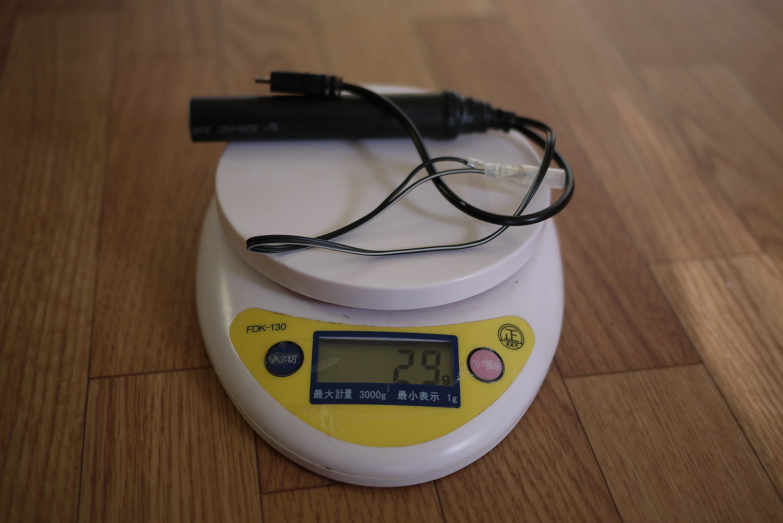
Weight: 29 grams
Weatherproof: Yes
Output: 5 volts DC (USB standard)
Input: 6 volts AC
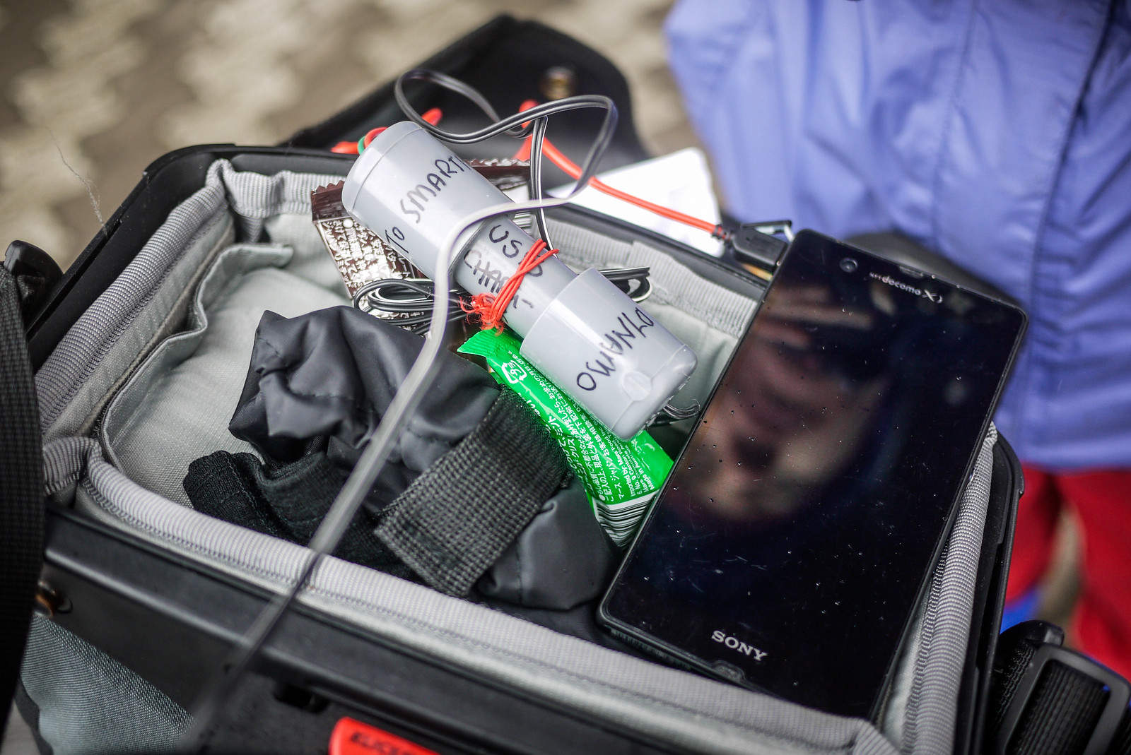
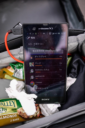
Efficiency: Will charge a Sony Experia Z smartphone at a rate of approximately 1% per 1km (with the smartphone turned off).
Charge start: 5.5km/h
Weight
What this device does
When charging your smartphone using a wall charger or your laptop’s USB, the electricity going into your phone is direct current (DC) at 5 volts. A bicycle dynamo hub, however, usually creates electricity in the form of alternating current (AC), at 6 volts. So, we’ve got to change the electricity created by the dynamo hub (6V AC) into the same type as what comes out of your smartphone wall charger or your laptop’s USB (5V DC). That’s what this device does.
Disclaimer: I know nothing about electronics. This charger has worked well for me so far (about 1,000km of cycle touring), but it may turn on you and eat your smartphone’s innards alive, rendering it a useless shell. Also, note that in very hilly terrain where constant high cycling speeds are expected (on the downhills), the charger may not cope with the high voltage output from the dynamo (voltage output often varies depending on speed) (thanks to commenter Prashant for the real-world observation). This may mean a need to unplug the charger on long, fast downhills. If you’d rather let someone else take the responsibility for your delicate electronics, check out the Bright-Bike Revolution (amazing value for a solid charger) or the Busch & Mueller Luxos IQ2 headlight with USB charging built in, or the Tout-Terrain Plug II.
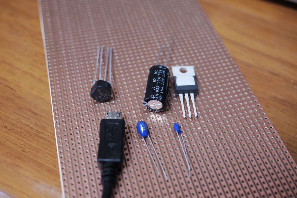
What you need
- Parallel stripboard (example)
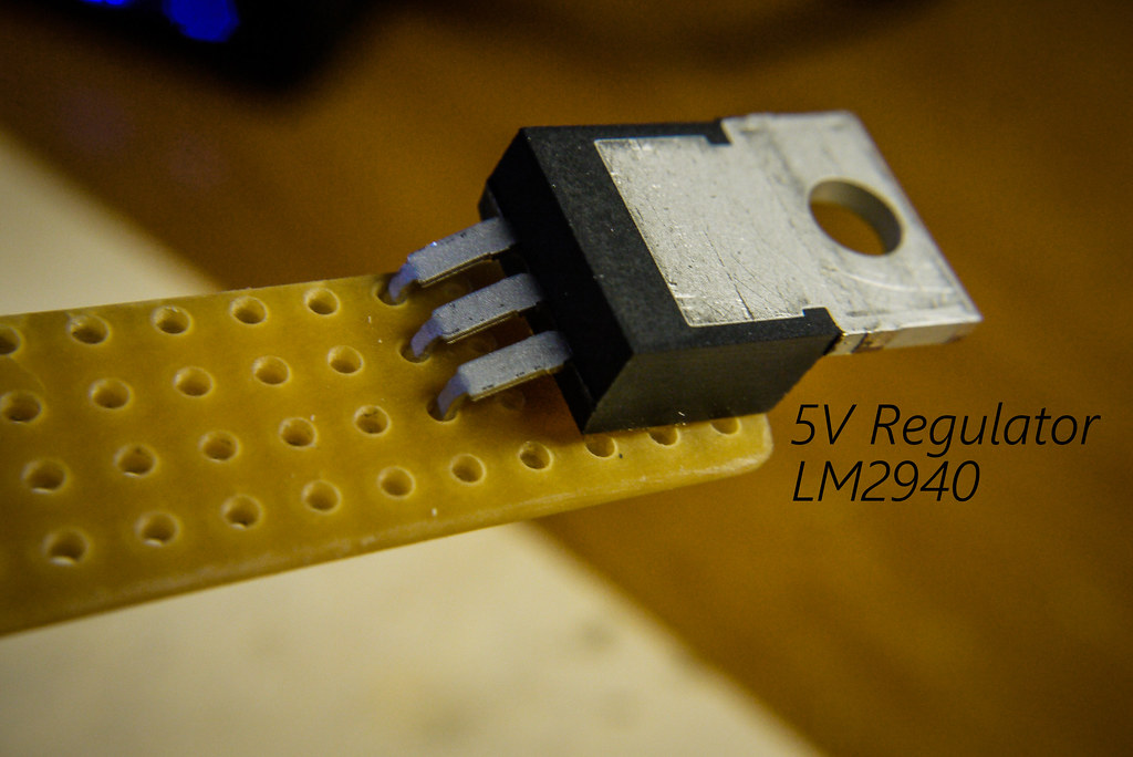
- 5 Volt Regulator LDO LM2940 (example – max input voltage 26V) (changes 6V to 5V)
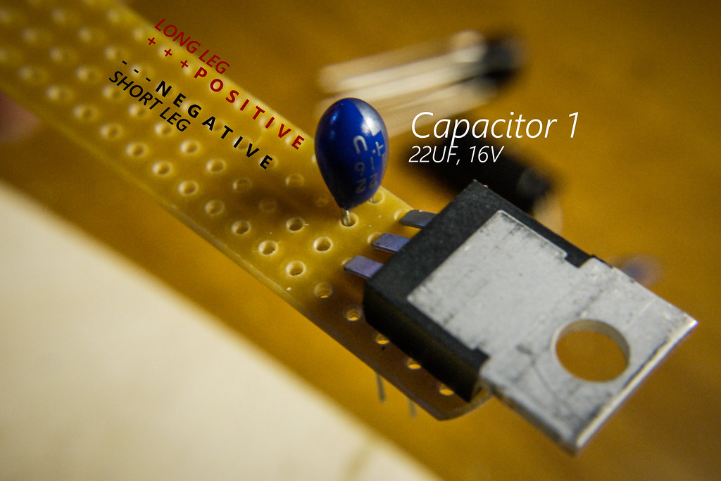
- Capacitor 1 (Tantalum bead, 16V 22µF) (example)
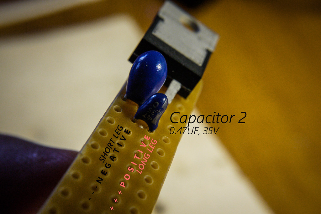
- Capacitor 2 (Tantalum bead, 35V 0.47µF) (example)
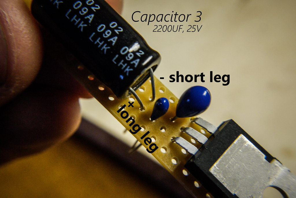
- Capacitor 3 (Electrolytic capacitor, 25V 2200µF) (example)
- The capacitors help keep the flow of electricity steady as you slow down and speed up on your bike (see Wikipedia for more).
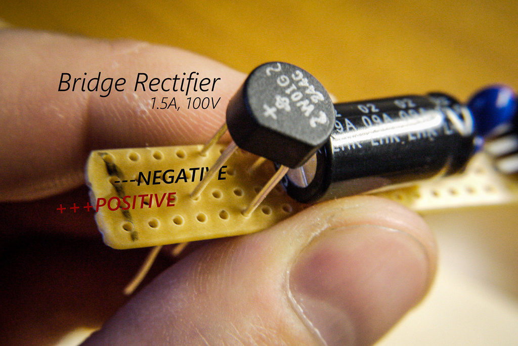
- Bridge Rectifier, 1.5A, 100V (example) (changes the input from AC to DC)
- Micro-USB terminal (example; you’ll cut off the big USB end and keep the small end, to plug into your device)
- Wire and terminals to attach to dynamo outlets
- A case of some kind to hold the electronics
How to Make it
Step 1
Cut the veroboard (stripboard) into an oblong, 4 holes wide by approximately 25 holes long. I did this by scoring the board with a craft knife on both sides and then snapping it.
Step 2
Start to populate your board. On the capacitors, the long leg is positive. Click on the photos for a larger version.
Step 3
This step can be tricky…aligning the bridge rectifier in place. Note the polarity (positioning of the negative and positive legs).
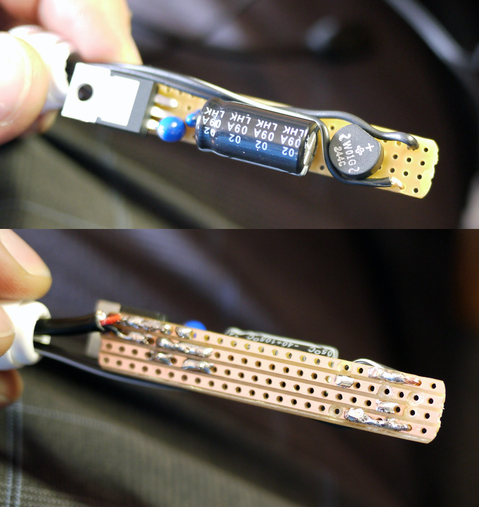
Looking from the top, your board should now look something like this.
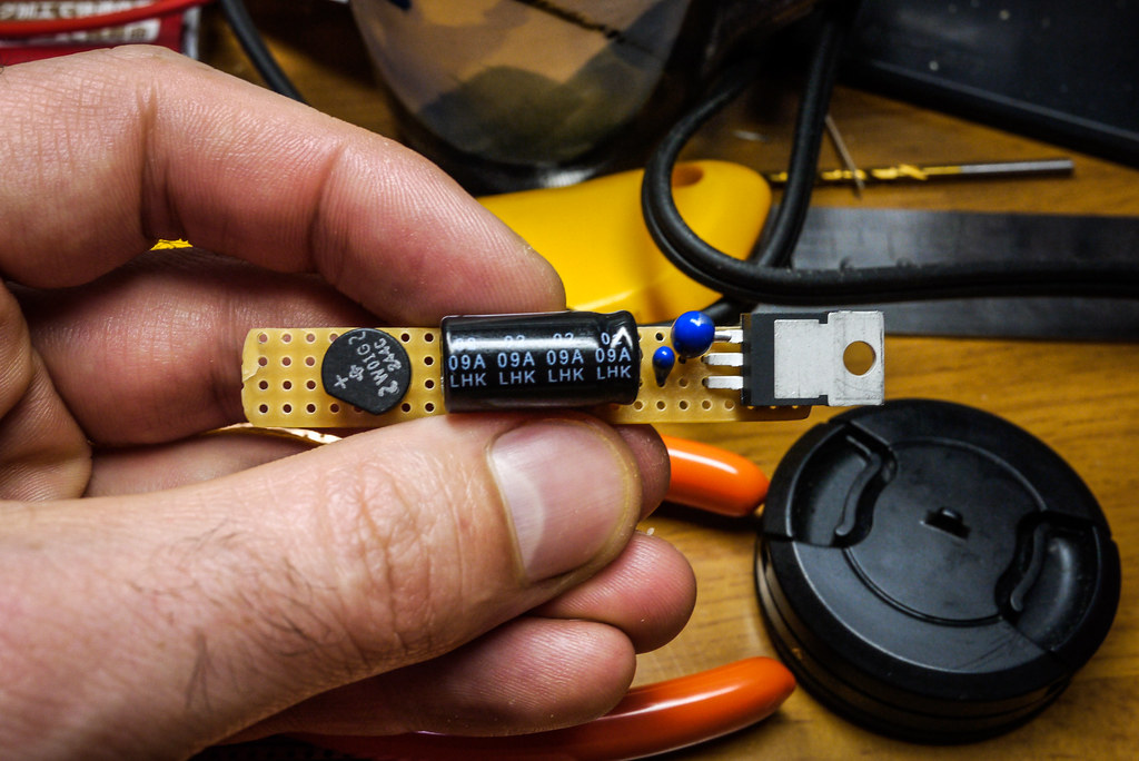
You can now go about carefully soldering the parts in place at the rear of the board. Take care not to overheat the parts, and make sure not to ‘connect’ any of the copper strips on the stripboard with stray bits of solder.
Post-soldering should look something like below. Ignore all the drill-marks, except for the one at the bottom. You need that one to stop current going directly to the regulator (LM2940). Holes can be made by hand-turning a 5mm drill bit.

Step 4
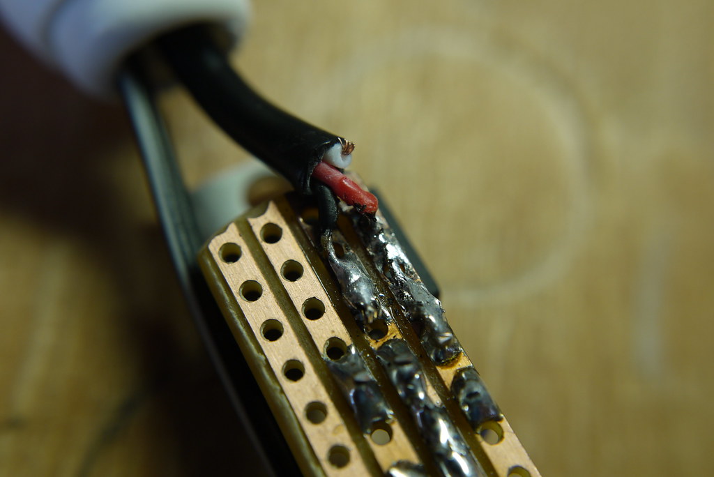
Prepare your micro-USB connector by butchering a cheap USB to micro-USB cable, discarding the big USB end. We will attach this to the circuit-board, and it will plug into your smartphone. Frustratingly, USB cable inner wire colors are sometimes different (like, green for negative). But most of the time, they will be red (positive), black (negative) and white (data). You won’t be needing the white wire, so you can cut it short.

Step 5
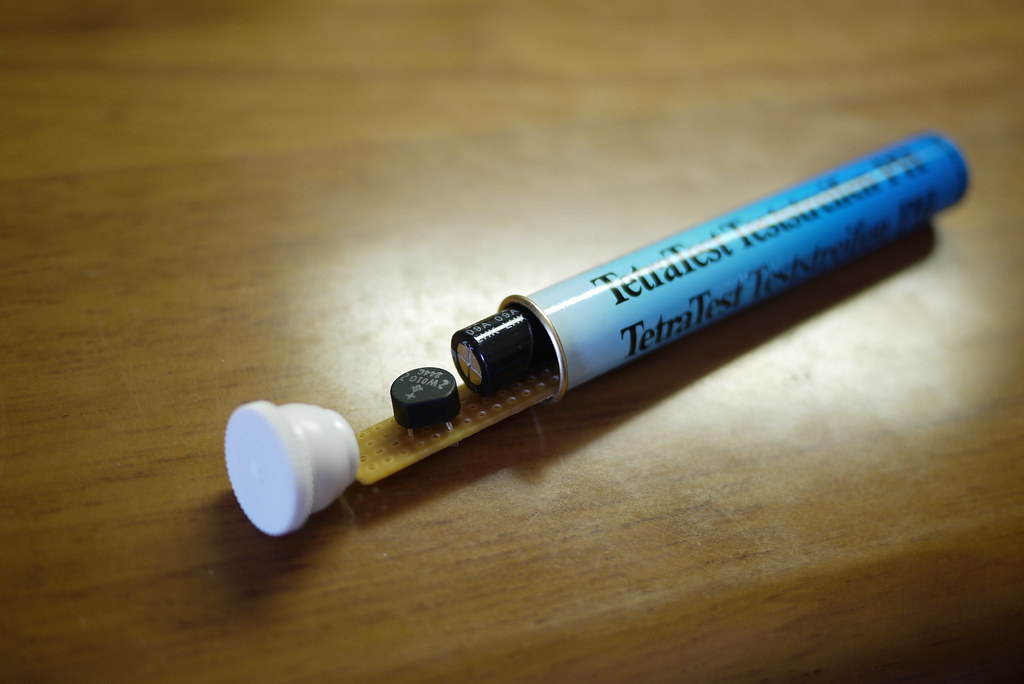
Before attaching the micro-USB cable to the circuit-board, a suitable case needs to be found. I happened to have an old fish-tank PH level tester container hanging around that was a perfect size.
Step 6
Container sorted, time to thread the cables through the openings and solder them to the circuit board. I first attached the micro-USB cable. Red on the positive line, black on the negative line.
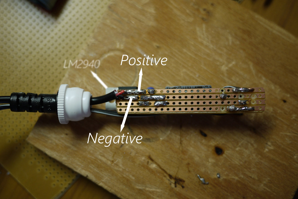
Next, attach the wires that will run from the dynamo hub. The polarity (negative and positive direction) here doesn’t matter at all; the bridge rectifier has magic fairies inside that sort all that out.
Step 7
Install the circuit board in a suitable container. Before sealing the container up properly, now may be a good time to hook the unit up to a dynamo hub and smartphone to check that everything is working.
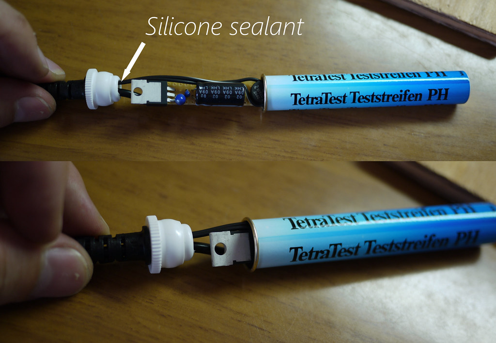
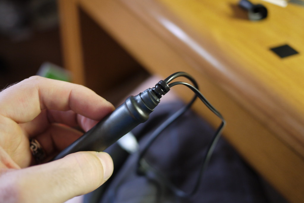
Step 8 (optional)
This step is not essential, but I wanted to make this unit as weather-proof as possible. Using a couple of different size heat-shrink tubing, I covered the whole thing up, making it very weather-proof.
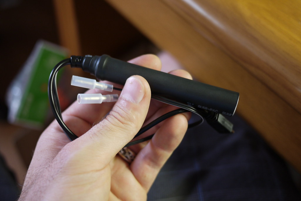
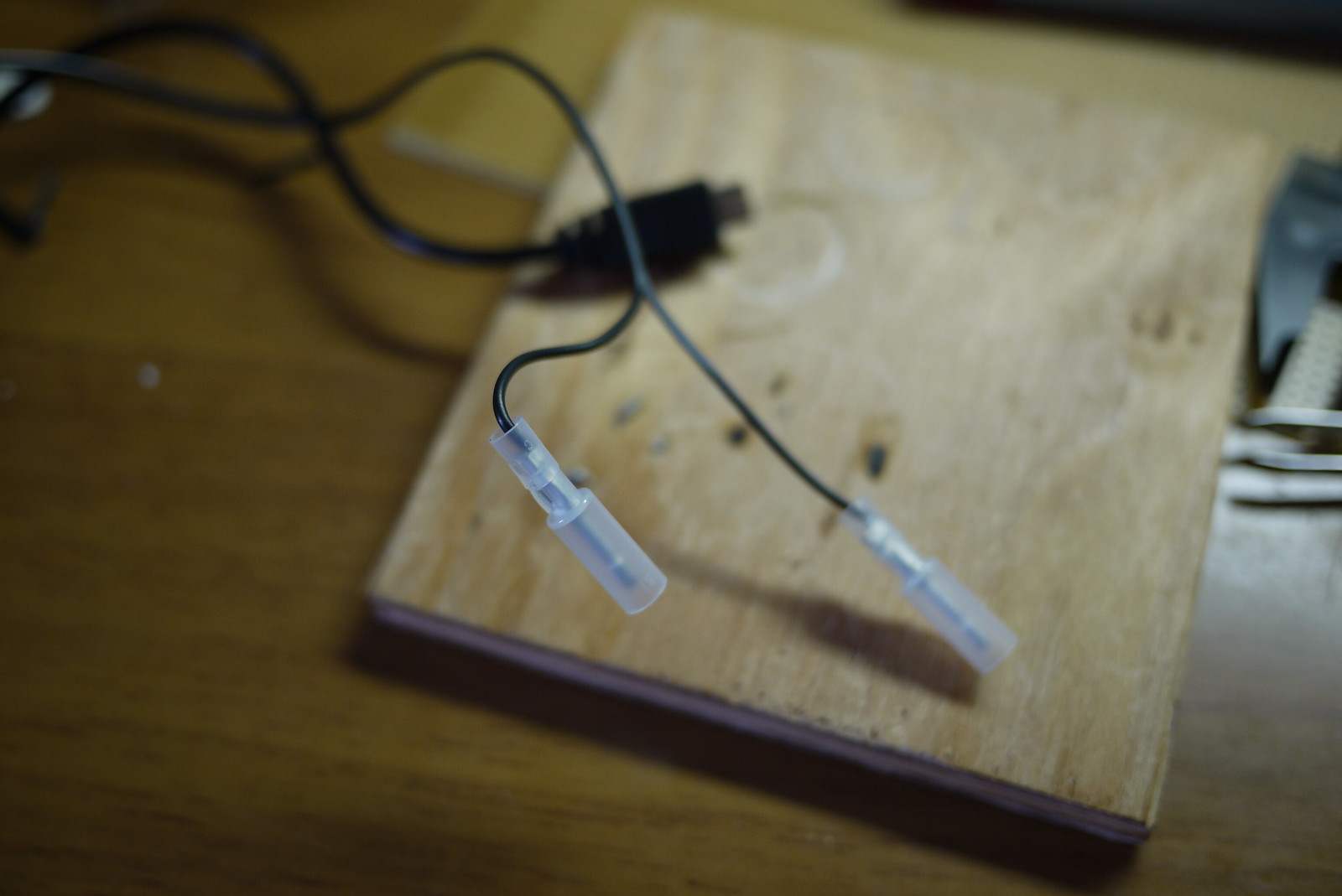
Step 9
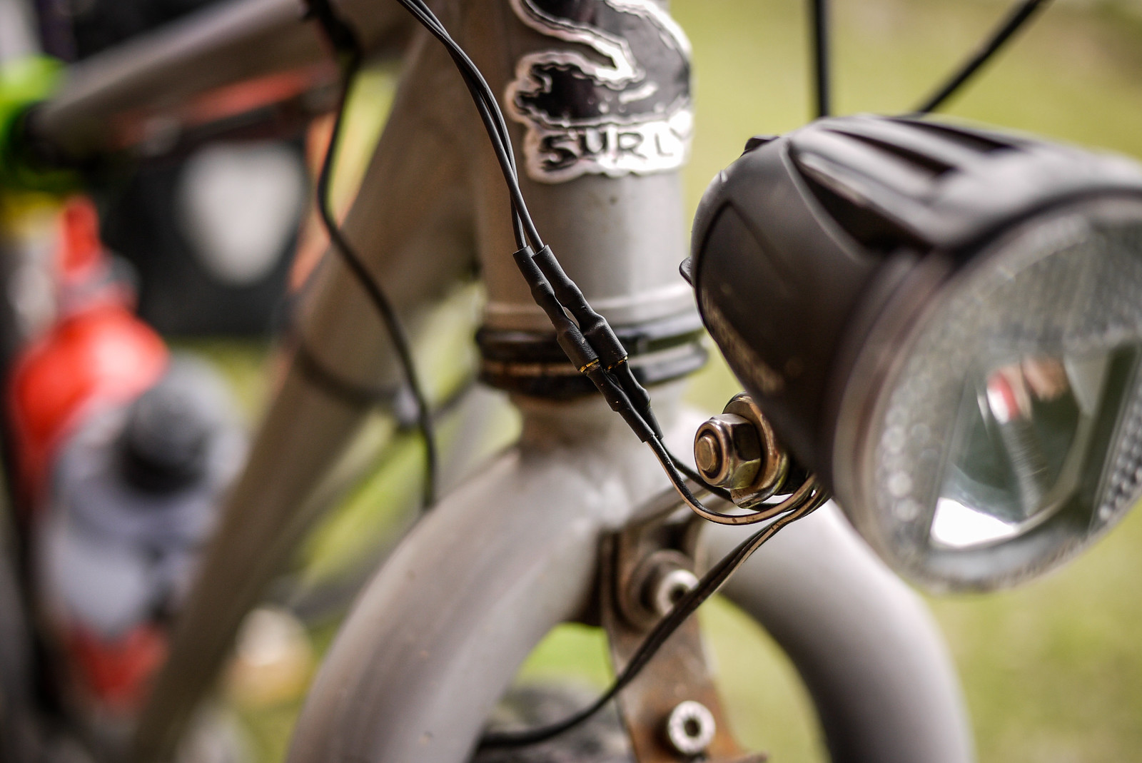
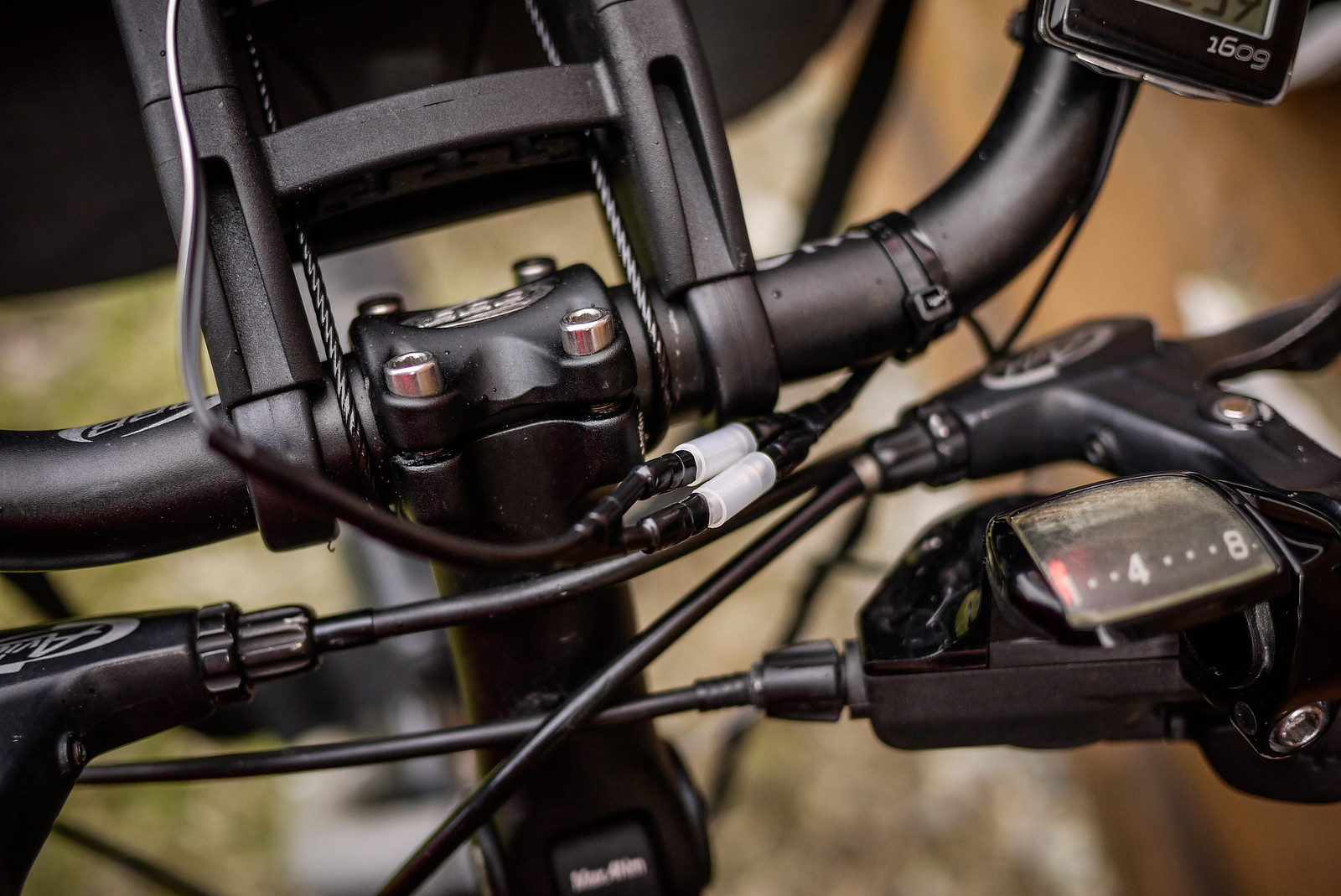
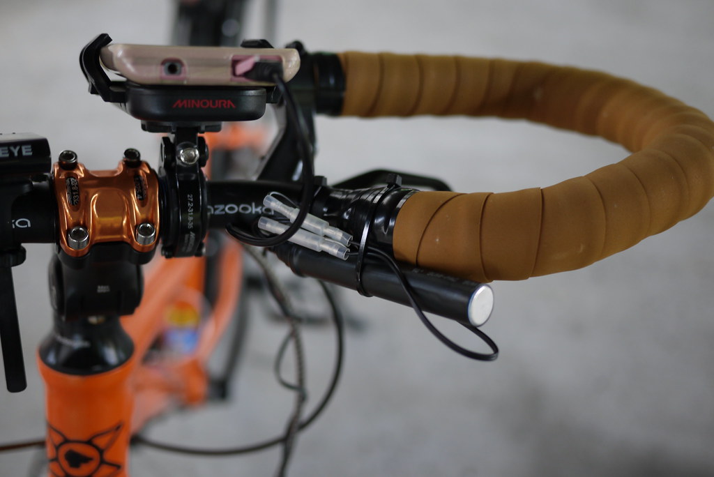
I wanted to be able to easily attach and remove the charger from my bike. The only time I use it is when I am cycle touring (about twice a year). This was easily done by using simple male/female connectors. The wire running from my hub to the female connectors is on my bike all the time, and I can just connect the charger when I need to.
Wrap-up
Performance in the real world
This is the second charger I have made (using the exact same circuitry). The first one ended up in a PVC pipe casing, which is ugly and bulky. It works exactly the same as this new slick-cased version. Using the PVC-pipe-case version, I was able to get around 1% charge for every 1km pedaled on a laden, flat-terrain four-day cycle tour (with the phone powered off). That was charging a Sony Experia Z smartphone, which has a very large battery (2330mAh). With an iPhone, with its smaller 1440mAh, this might be more like 2% charge per 1km.
In any case, with the phone powered off, it will charge fully over a full day of cycling. It does not put out enough charge to keep up with intensive computing tasks like Google Map Navigation. That is, with the screen on all the time, plus the GPS running, the battery will still run down even while charging.
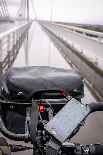
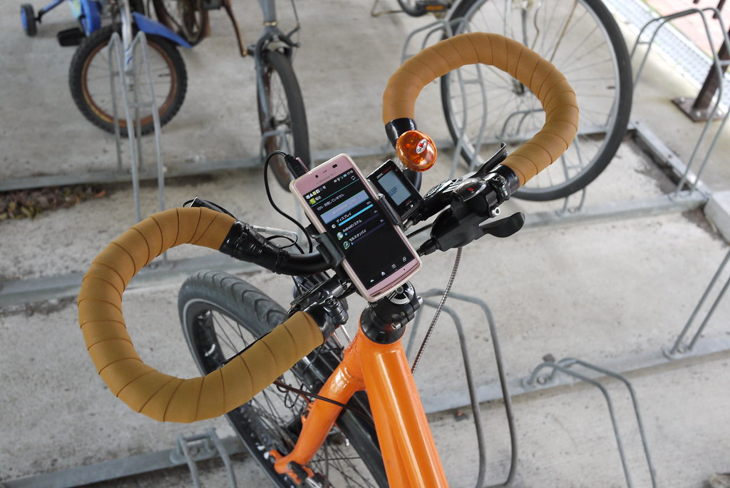
My wife has claimed this new version as her own, so I am still stuck with the PVC pipe version. On her bike, this is the set up we have at present (she doesn’t use a handlear bag). Here, the charger is attached using a cable tie, in the photo at the top of this post, we have attached a velcro strap, which will make attaching/removing the charger easier.
Update (2014/06/08)
Thanks to commenter Prashant, I’ve just found out that you can buy a perfectly good charger for only US$30 or so: The Biologic ReeCharge Dynamo Kit. See the demo on Youtube https://www.youtube.com/watch?v=tnlB68KulcE, and looks like you can get it on Amazon: http://www.amazon.com/BioLogic-Reecharge-Dynamo-Kit/dp/B006OSQUNI. For that price, the only reason you’d ever need to make your own device is if you’re really into DIY! Official page for the kit here: http://www.thinkbiologic.com/products/reecharge-dynamo-kit-micro-usb-cable
Update (2014/09/21)
Note Viktoras’s comment that the Biologic Reecharge may not give enough output for some devices.


119 thoughts on “DIY Bicycle Dynamo USB Charger for Smartphones and Battery Packs”
Are the connections of the solder iron between the different capacitors necessary, cause my teacher said the copper lines are enough connection.
BTW: Sorry for the bad english 😉
Is it OK to use a soldering pistol for this? Cuz I don’t have a soldering iron
Is it OK to use a soldering pistol for this. Cuz I don’t have a soldering iron
hi Rob Thomson
very nice and good.
what kind of dynamo hub that you used for this bicycle..?
It is an Alfine dynamo hub (https://www.amazon.com/Shimano-DH-S501-Alfine-Dynamo-Disc/dp/B007M817QE).
Hi Rob,
Me and a friend are trying to charge a smartphone with your charger and the energy from a sterling engine.
Do you think it will go well?
Because we do not know, if the sterling engine is creating enough energy.
PS: I like your work pretty much.
Short answer is I have no idea…however, if your sterling engine can turn a bicycle dynamo, then of course it will work 🙂
Hi, thanks for the guide.
I see a lot of comments describing risks with this when plugging in devices. I intend to only connect a battery pack which requires a 5V 1A input to the hub, and then charge my devices from the pack. Can anyone tell me if there are obviously foreseeable problems with doing this? (I know nothing about electronics)
Thanks
Using a battery pack between the charger and your electronic device will definitely be the safer option.
Hi. Last year I’ve built a USB charger following this project! Thanks for the ideas and congratulations! Since few days ago I’ve upgraded my byke with a hub dynamo (Shimano DH-3N80) I’d like to know if I need to protect this charger from overvoltage risk! My hub was equipped with external overvoltage protection to put between the front and the rear light… do I have to use it to protect the USB charger?
Thanks!
Francesco
This text is invaluable. Where can I find out more?Very descriptive post, I loved that a lot.
Will there be a part 2?
Fantastic analysis ! I Appreciate the points ! Does anyone know if I can obtain a blank AL ADoR 40V example to complete ?
Pingback: Xperia 充電器
I’m sorry to bother you but i have one question:
Which dynamo should I use, can you please link me one that works with this ciruit?
Thanks
Pablo
I am using a Shimano Alfine dynamo hub, but most other 6v 3W AC hubs should work fine.
Pingback: Quora
There’s many reasons why this wont work, the main one being voltage dropout. Your bridge and LDO are inefficient and waste enough milliwatts to make it ineffective with devices that require more current. What’ll happen is devices will show themselves as charging but will actually discharge.
Next up, with no load and going downhill a Shimano 3W dynamo can give out 65v AC or more, which will fry your LDO. Likely that small silicon recifier will breakdown as well, potentially dumping AC into your USB device.
Use something designed for the job!
https://d1.igaro.com
Looks like a very nice unit!
Hiii Rob!!
Actually I need a circuit diagram of this b’coz I am Getting problem in soldering the components.
Plz reply!!
Check out the links at the beginning of the post; they have circuit diagrams.
Nice, i have a question, what if i get those “usb wall chargers”, its says: input ac 100-240v, output dc 5.0v == 500mA
Doesnt it do the same thing? convert AC to DC to charge the phone, im thinking, all i need to do is set the wire from the dynamo to the wall charger and connect an usb cable to whatever device.
yup, it works, i just tested with an “usb wall charger” i connected the usb wall charger to the dynamo and then my phone into the charger, perfect.
Is it possible to use a female usb connector instead of the micro usb?
I just solder a female usb connector to it and then use a cable, so I can use diferent usb cables. Is that possible?
I build a Frankenstein of this charger, based on the buck converter recommendation above.
I bought one of these
https://www.amazon.ca/DROK-Stepdown-Converter-Regulator-Voltmeter/dp/B00IWOPS8K/ref=sr_1_5?ie=UTF8&qid=1437072211&sr=8-5&keywords=buck+converter
It was rated to 40V input.
I then connected a bridge rectifier to it, with the big capacitor between the rectifier and buck. It worked great, when I went ‘slow’.
I went down a hill at a decent speed, and the cap blew, and I suspect the buck is fried as well.
Yes, that is standard, Shimano dynamo’s are unsaturated and 65V is plausible downhill. I’ve seen 80V and the video on youtube shows over 100V!
Hi! I bought a Kemo usb charger befor but now im so eager to make the one which you explain here!
Yhis Kemo really sucks! It always cut the electricity When the speed is around 30 km/h. So i can’t charch my galexy note2. my dynamohub is shimano 6v and 3w.
Dose you know why it happend even in low speed?
Hello,
thanks for the great post, i really want to try making it however i dont have the components, do you know if there is ready-made product that do the same or better if you can make and sell me one of yours?
The Biologic dynamo kit is quite good value (see the links at the top of the post).
Thanks for the post.
Am I understanding correctly that you have wires leading from the dynamo to your lights all the time? Do you have a switch to select lights vs USB, or did you just split the output wire?
At the moment, at least on my wife’s bike, the charger is plugged into the rear-light output wires on the B+M Lumotec front light (we don’t have a rear dynamo light on her bike at the moment). If we did have a dynamo-powered rear light on there, we’d either have to wire the charger direct to the hub, or make a switch.
Oh, and on my bike, with the rear dynamo light, I’ve just got the charger connection wires directly wired to the hub.
Could you not just have a single wire attached to the hub, split it between the lights and the USB circuit, and have a simple on/off switch on the USB circuit housing? That seems like it would still feed the USB circuit fine when the lights are off, but protect it during periods where there is no load on the hub output. Maybe I’ve missed something?
You could indeed. I’m just lazy 🙂
I am beginner, draw a schematic plz