
Cost and Specs
Total cost: approx. US$15 (parts only; you need tools such as soldering iron etc.)
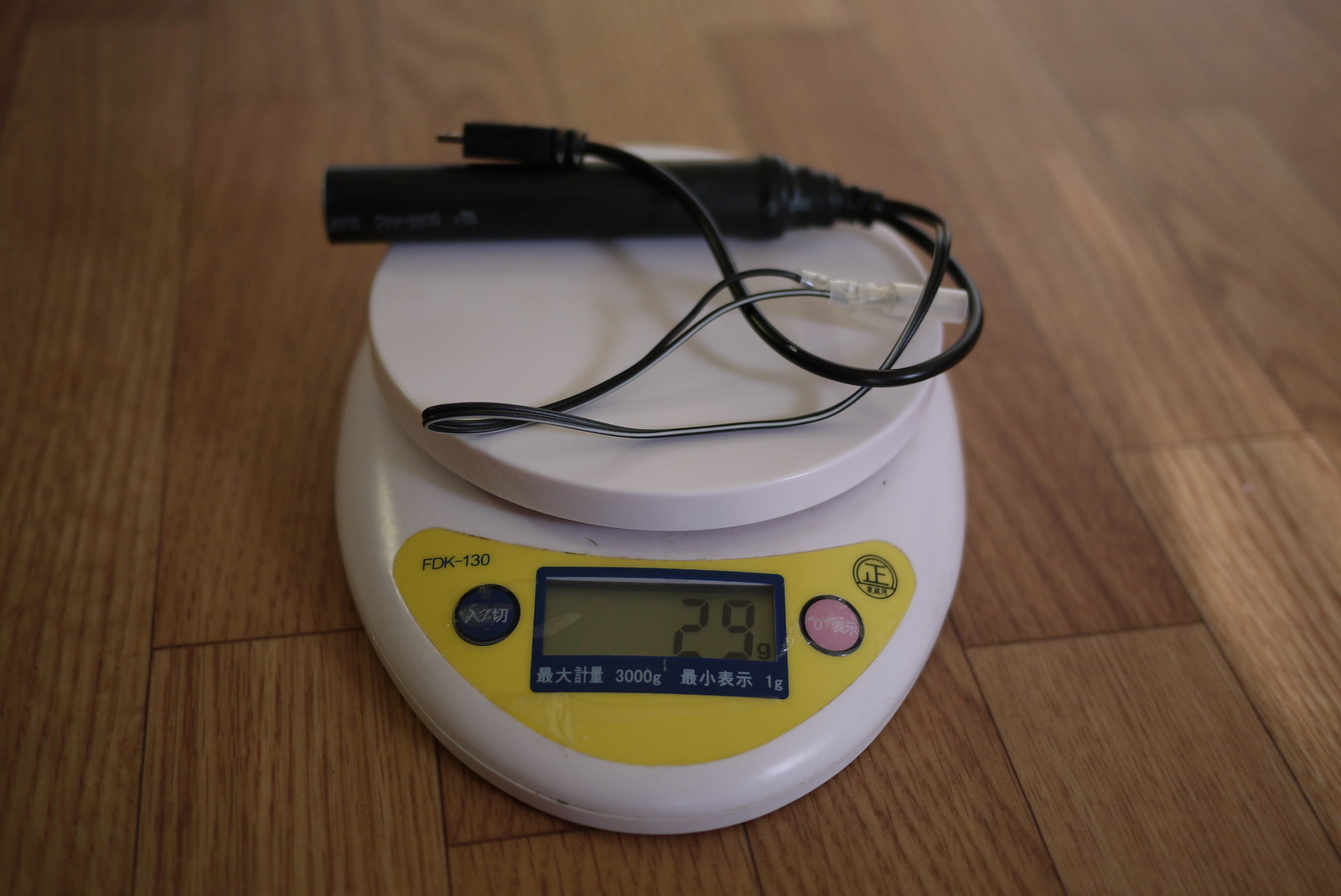
Weight: 29 grams
Weatherproof: Yes
Output: 5 volts DC (USB standard)
Input: 6 volts AC
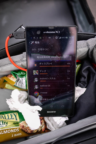
Efficiency: Will charge a Sony Experia Z smartphone at a rate of approximately 1% per 1km (with the smartphone turned off).
Charge start: 5.5km/h
Weight
What this device does
When charging your smartphone using a wall charger or your laptop’s USB, the electricity going into your phone is direct current (DC) at 5 volts. A bicycle dynamo hub, however, usually creates electricity in the form of alternating current (AC), at 6 volts. So, we’ve got to change the electricity created by the dynamo hub (6V AC) into the same type as what comes out of your smartphone wall charger or your laptop’s USB (5V DC). That’s what this device does.
Disclaimer: I know nothing about electronics. This charger has worked well for me so far (about 1,000km of cycle touring), but it may turn on you and eat your smartphone’s innards alive, rendering it a useless shell. Also, note that in very hilly terrain where constant high cycling speeds are expected (on the downhills), the charger may not cope with the high voltage output from the dynamo (voltage output often varies depending on speed) (thanks to commenter Prashant for the real-world observation). This may mean a need to unplug the charger on long, fast downhills. If you’d rather let someone else take the responsibility for your delicate electronics, check out the Bright-Bike Revolution (amazing value for a solid charger) or the Busch & Mueller Luxos IQ2 headlight with USB charging built in, or the Tout-Terrain Plug II.
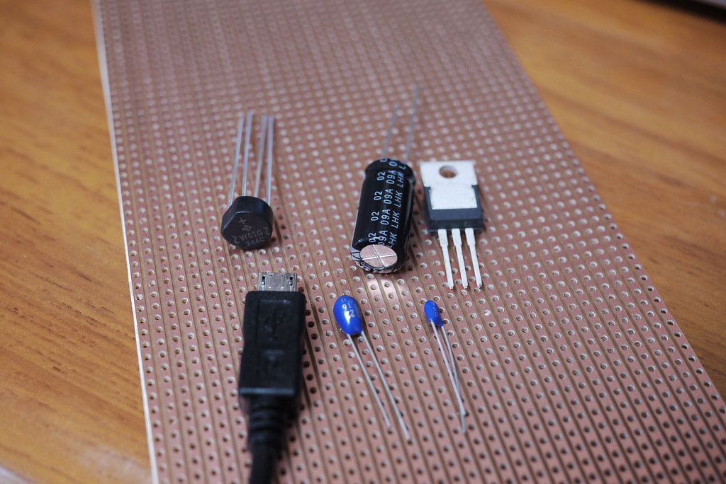
What you need
- Parallel stripboard (example)
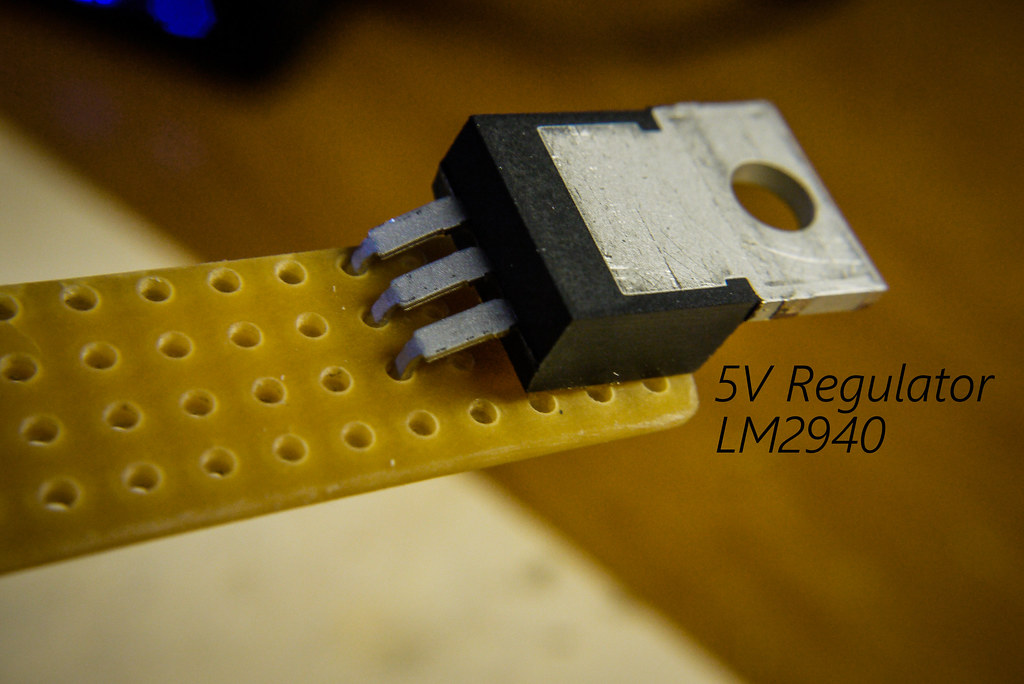
- 5 Volt Regulator LDO LM2940 (example – max input voltage 26V) (changes 6V to 5V)
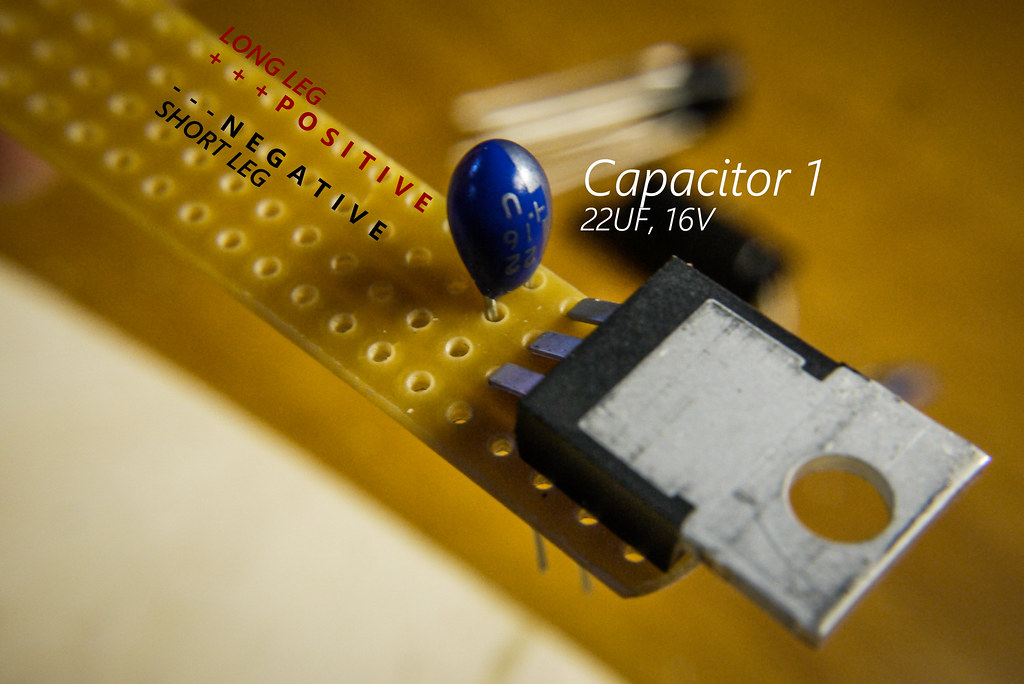
- Capacitor 1 (Tantalum bead, 16V 22µF) (example)
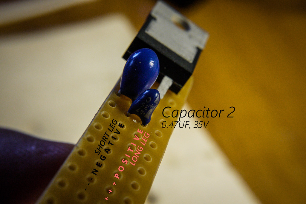
- Capacitor 2 (Tantalum bead, 35V 0.47µF) (example)
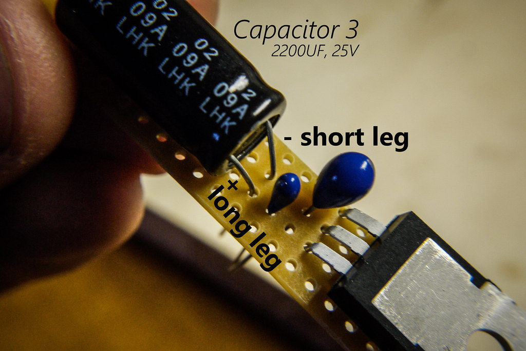
- Capacitor 3 (Electrolytic capacitor, 25V 2200µF) (example)
- The capacitors help keep the flow of electricity steady as you slow down and speed up on your bike (see Wikipedia for more).
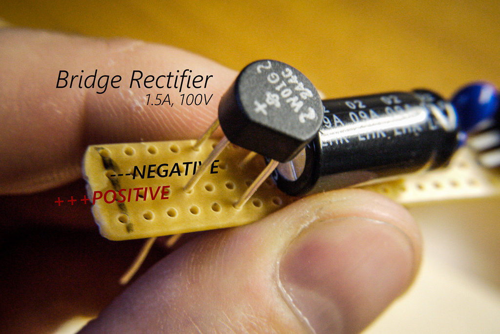
- Bridge Rectifier, 1.5A, 100V (example) (changes the input from AC to DC)
- Micro-USB terminal (example; you’ll cut off the big USB end and keep the small end, to plug into your device)
- Wire and terminals to attach to dynamo outlets
- A case of some kind to hold the electronics
How to Make it
Step 1
Cut the veroboard (stripboard) into an oblong, 4 holes wide by approximately 25 holes long. I did this by scoring the board with a craft knife on both sides and then snapping it.
Step 2
Start to populate your board. On the capacitors, the long leg is positive. Click on the photos for a larger version.
Step 3
This step can be tricky…aligning the bridge rectifier in place. Note the polarity (positioning of the negative and positive legs).
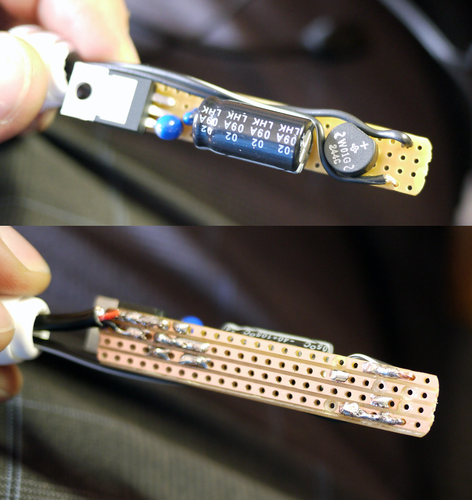
Looking from the top, your board should now look something like this.
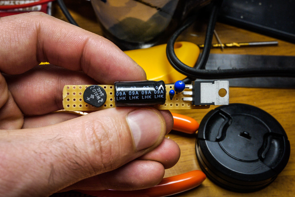
You can now go about carefully soldering the parts in place at the rear of the board. Take care not to overheat the parts, and make sure not to ‘connect’ any of the copper strips on the stripboard with stray bits of solder.
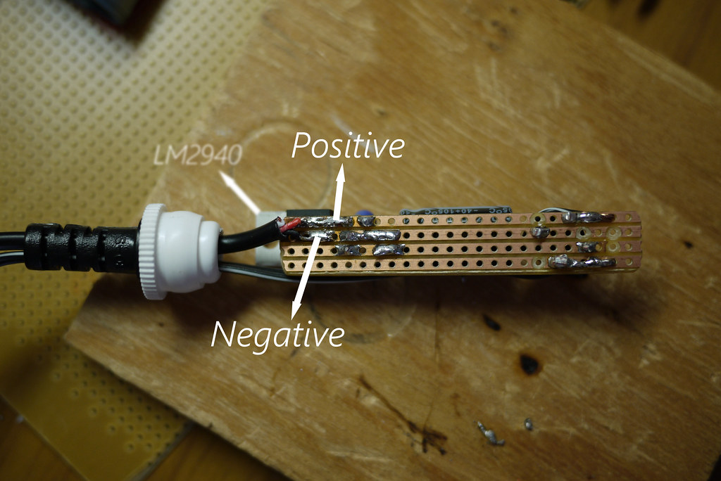
Post-soldering should look something like below. Ignore all the drill-marks, except for the one at the bottom. You need that one to stop current going directly to the regulator (LM2940). Holes can be made by hand-turning a 5mm drill bit.

Step 4
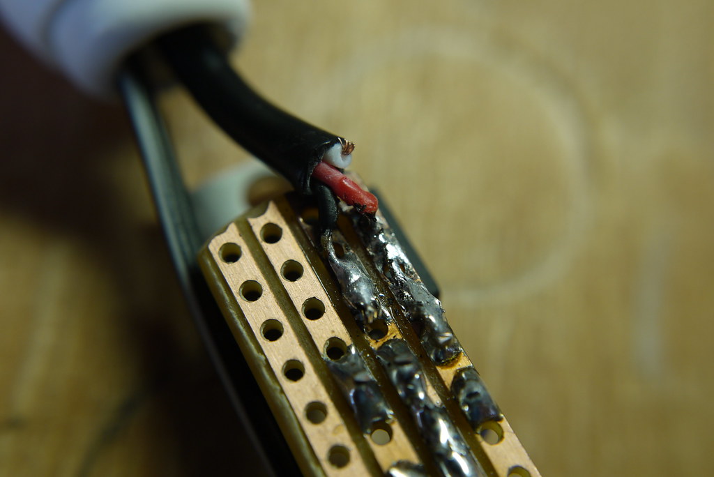
Prepare your micro-USB connector by butchering a cheap USB to micro-USB cable, discarding the big USB end. We will attach this to the circuit-board, and it will plug into your smartphone. Frustratingly, USB cable inner wire colors are sometimes different (like, green for negative). But most of the time, they will be red (positive), black (negative) and white (data). You won’t be needing the white wire, so you can cut it short.

Step 5
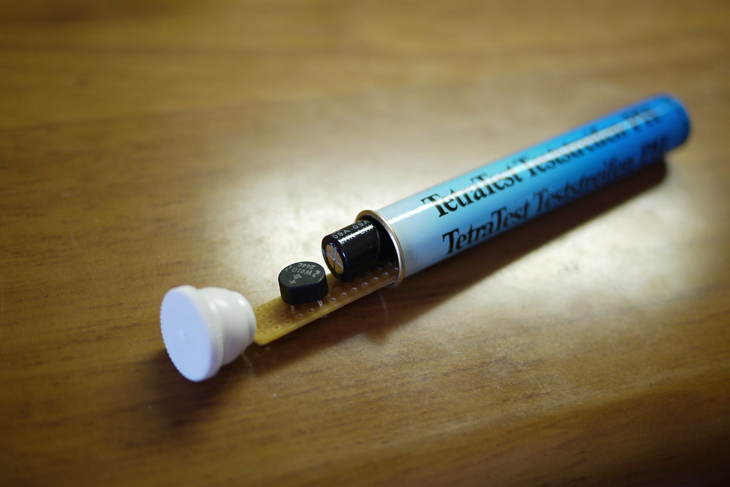
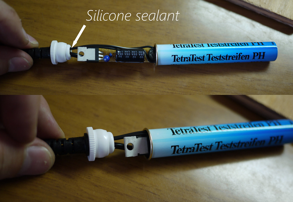
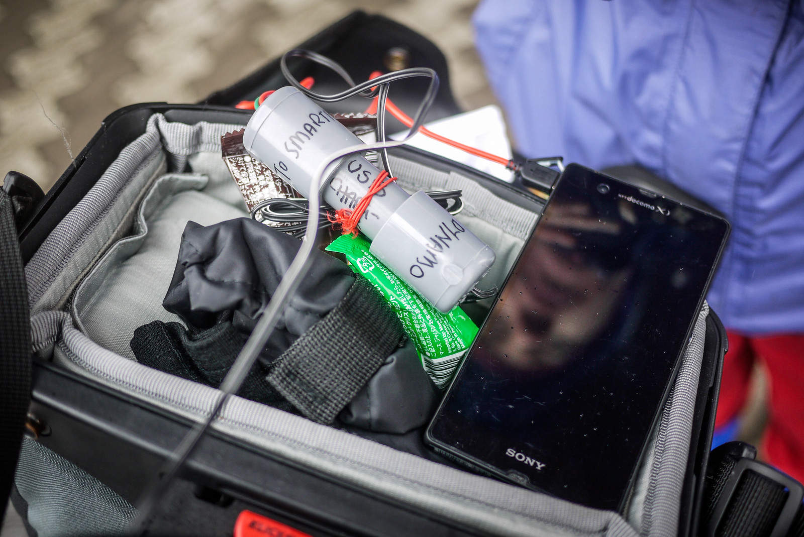
Before attaching the micro-USB cable to the circuit-board, a suitable case needs to be found. I happened to have an old fish-tank PH level tester container hanging around that was a perfect size.
Step 6
Container sorted, time to thread the cables through the openings and solder them to the circuit board. I first attached the micro-USB cable. Red on the positive line, black on the negative line.
Next, attach the wires that will run from the dynamo hub. The polarity (negative and positive direction) here doesn’t matter at all; the bridge rectifier has magic fairies inside that sort all that out.
Step 7
Install the circuit board in a suitable container. Before sealing the container up properly, now may be a good time to hook the unit up to a dynamo hub and smartphone to check that everything is working.
Step 8 (optional)
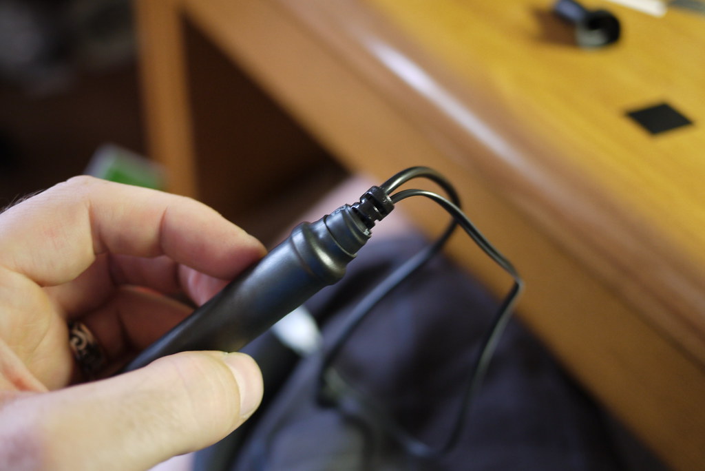
This step is not essential, but I wanted to make this unit as weather-proof as possible. Using a couple of different size heat-shrink tubing, I covered the whole thing up, making it very weather-proof.
Step 9
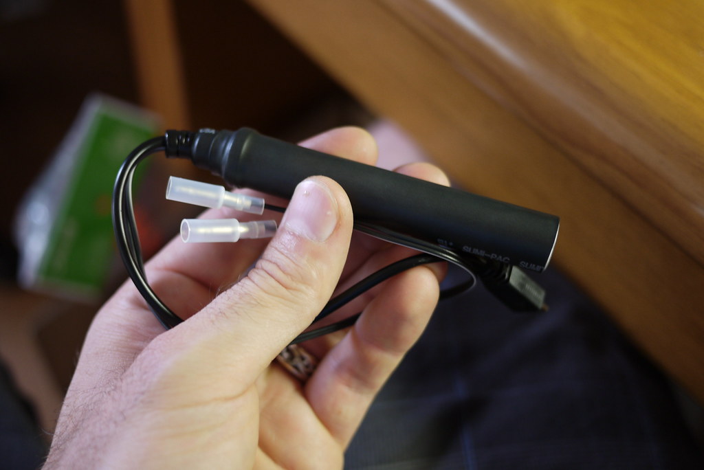
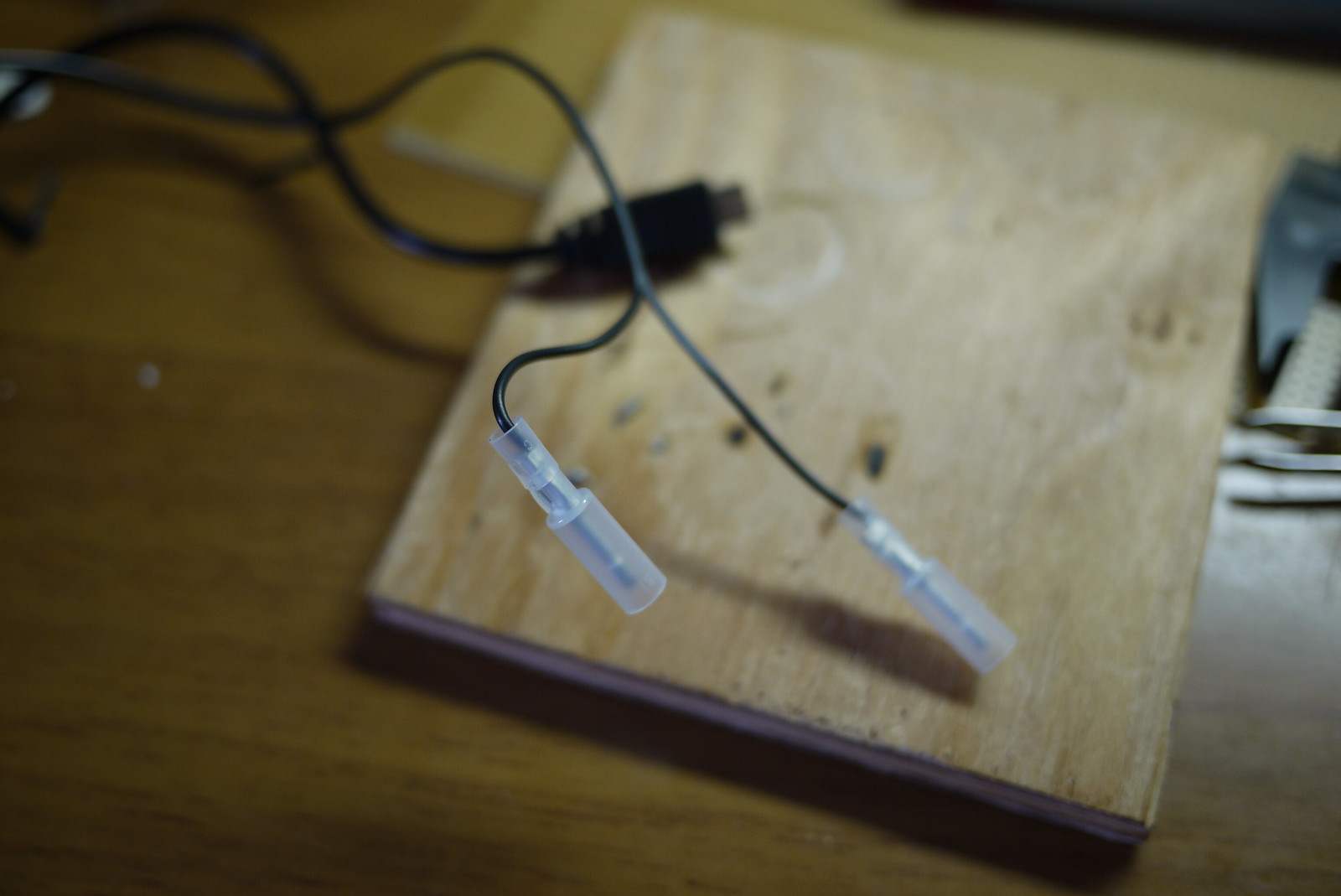
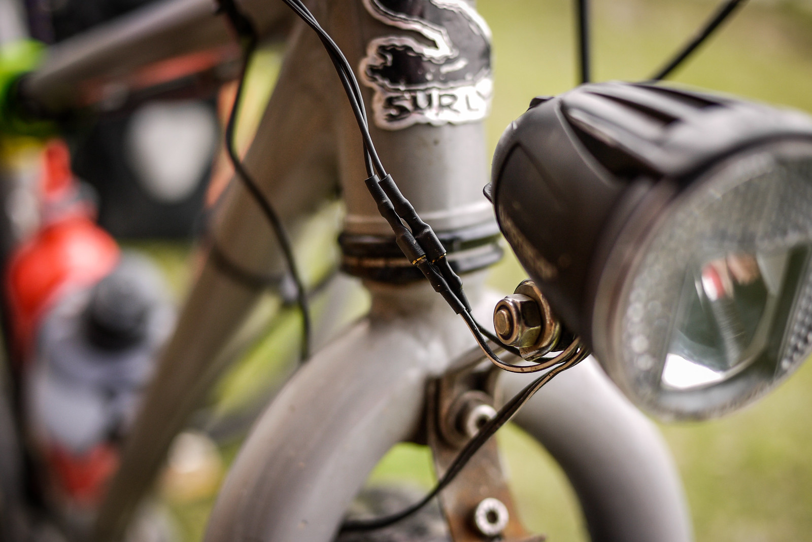
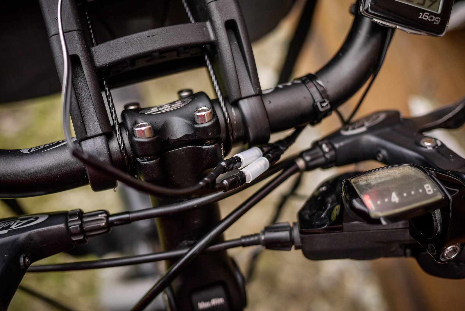
I wanted to be able to easily attach and remove the charger from my bike. The only time I use it is when I am cycle touring (about twice a year). This was easily done by using simple male/female connectors. The wire running from my hub to the female connectors is on my bike all the time, and I can just connect the charger when I need to.
Wrap-up
Performance in the real world
This is the second charger I have made (using the exact same circuitry). The first one ended up in a PVC pipe casing, which is ugly and bulky. It works exactly the same as this new slick-cased version. Using the PVC-pipe-case version, I was able to get around 1% charge for every 1km pedaled on a laden, flat-terrain four-day cycle tour (with the phone powered off). That was charging a Sony Experia Z smartphone, which has a very large battery (2330mAh). With an iPhone, with its smaller 1440mAh, this might be more like 2% charge per 1km.
In any case, with the phone powered off, it will charge fully over a full day of cycling. It does not put out enough charge to keep up with intensive computing tasks like Google Map Navigation. That is, with the screen on all the time, plus the GPS running, the battery will still run down even while charging.
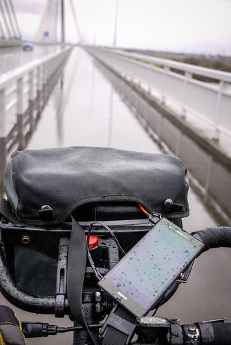
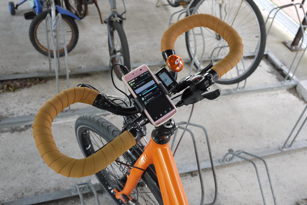
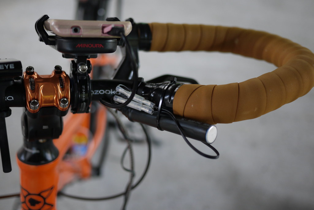
My wife has claimed this new version as her own, so I am still stuck with the PVC pipe version. On her bike, this is the set up we have at present (she doesn’t use a handlear bag). Here, the charger is attached using a cable tie, in the photo at the top of this post, we have attached a velcro strap, which will make attaching/removing the charger easier.
Update (2014/06/08)
Thanks to commenter Prashant, I’ve just found out that you can buy a perfectly good charger for only US$30 or so: The Biologic ReeCharge Dynamo Kit. See the demo on Youtube https://www.youtube.com/watch?v=tnlB68KulcE, and looks like you can get it on Amazon: http://www.amazon.com/BioLogic-Reecharge-Dynamo-Kit/dp/B006OSQUNI. For that price, the only reason you’d ever need to make your own device is if you’re really into DIY! Official page for the kit here: http://www.thinkbiologic.com/products/reecharge-dynamo-kit-micro-usb-cable
Update (2014/09/21)
Note Viktoras’s comment that the Biologic Reecharge may not give enough output for some devices.


119 thoughts on “DIY Bicycle Dynamo USB Charger for Smartphones and Battery Packs”
Can I see your Prototype about this project?
Sorry, did’t make a prototype…just made it haha!
Hello. I should have searched more before I started doing it. I am training at the moment to take a longer bike touring in home birth country in Balkans this year. For this I need circuitry to make 6V 3W alternator to reliable 5V 0.5A charger. Your design is dang good! It will go inside steering tube nicely. 😉
I need reliable design as hub alternators inherently create fluctuations in generated Voltages and AC frequencies.
Thanks in advance for assistance.
Thanks for publishing your exploits
Capacitor 2 seems unnecessary since you connect it in parallel (thus adding both capacitances) with the relatively huge Capacitor 3. It’s like putting a mouse on top of an elephant for added weight.
Other than that, it’s a useful guide, I’m going to try to make a charger too. Thanks.
Hi guys,
is this build capable to be used with old moped magneto power generation in average 6V (sometimes much more) and 15W? What regulator, capacitor and diode would you recommend? Maybe also fuse to be sure?
Thanks for advice
Peter
Sorry Peter, I’m not sure!
hello sir,
i am planning to make a more complicated one with higher efficiency.
did the lm7805 hold it with 60-70km/h downhill or did it burn the lm7805.
becauce every dynamo makes around 0,81-0,96v per km/h.
so 47km/h downhill means that the 38,07V would be too high for the LM7805.
the LM7805 can handle maximum of 37v at peak.
did you have any trouble with the voltage regiulator?
pls let me know.
Greetings from Holland,
Menoah
No problem with the voltage regulator at present…but we don’t do much more than 50km/h very often, so your mileage may vary!
Thanks for your reply
I’m doing the same project but using a standard ready made module from eBay. For the rectifier I’ve made my own from 4 Schottky diodes. This halves the voltage drop across the rectifier, to just 0.7v from 1.4v with the silicon rectifier you’re using. Also a bigger capacitor (4700uf) for better smoothing at slow speed. Finally an XL6009 LM2596s boost buck converter which works with as little as 3.5vdc and more stable generally. Mine is bigger however. I like your pipe mounting. I’m going to do that too and see if I can mount it in the fork headstock tube.
The commercial modules are hideously expensive.
Hello Richard,
could you share me the progress of your project?
i am trying to do the same.
i have bought a 3d printer so that i can make a model which goes into the fork steerer tube.
maybe we could team up so that we use eachother skills to make a even bette one.
pls let me know if youre interested.
Email me:
menoahgunzel.mg@gmail.com
or send me a whatsapp text +49176 8475 4920
Hello, I would very much to buy something like this, could you please let me know if you have one for sale? Thanks
We do not…but here’s a bunch of options: https://www.cyclingabout.com/best-dynamo-usb-chargers-bicycle-touring-bikepacking/
yeah i would need a scheme of the circuit as well… thanks anyway !
Glad it’s of some help!
I would like to do it without that stripboard but the circuit connections seem a kind confuse to figure out to me… thanks anyway, this is just what im looking for, a stable powering out of a fluctuating dynamo source 🙂
Hi,
You said you used a 25V 2200 microfarad capacitor, but you linked (the Farnell link) a 16V 2200 microfarad.
Will it work with a 16V instead of 25V or not ?
Thanks a lot for your guide anyways, Im bought the components and am working on this right now 🙂 Got an external battery and a 6V 3W Shimano Dynamo so hopefully it will work.
Not sure…all the best for the project!
I’m finished and success to make my Shimano dynamo hub working well by using this tutorial.
Many thanks for you Rob. Now I can go with my bike without loosing my moment because of low power.
Great to hear! Thanks for letting me know!
hi, i am also not an electronics engineer. i thought if you use a buck-boost (step up-down converter), it can handle higher voltages upto 48 volts. linear voltage regulators dissipate rest of the energy as heat (more risk of burning components or you need larger heat sink), on the other hand buck-boost is a capacitor based modules. And if you use normal brushed dc motor as a dynamo in place of hub dynamo, it will be easy and cheap to recreate it in any bicycle.
Interesting idea. Thanks!